
lifting device

A technology of lifting devices and interference parts, applied in the direction of lifting devices, etc., can solve problems such as uncontrollable speed and damage

Inactive Publication Date: 2019-07-30
QISDA SUZHOU +1
View PDF5 Cites 0 Cited by
  • Summary
  • Abstract
  • Description
  • Claims
  • Application Information

AI Technical Summary

Problems solved by technology

However, when the compression spring ejects the object from the seat, the speed of ejection cannot be controlled, and the object ejected instantly may sometimes frighten the user, or collide with surrounding objects and be damaged

Method used


Image

  • lifting device
  • lifting device
  • lifting device

Examples


Embodiment Construction

[0034] In order to have a further understanding of the purpose, structure, features, and functions of the present invention, the following detailed descriptions are provided in conjunction with the embodiments.

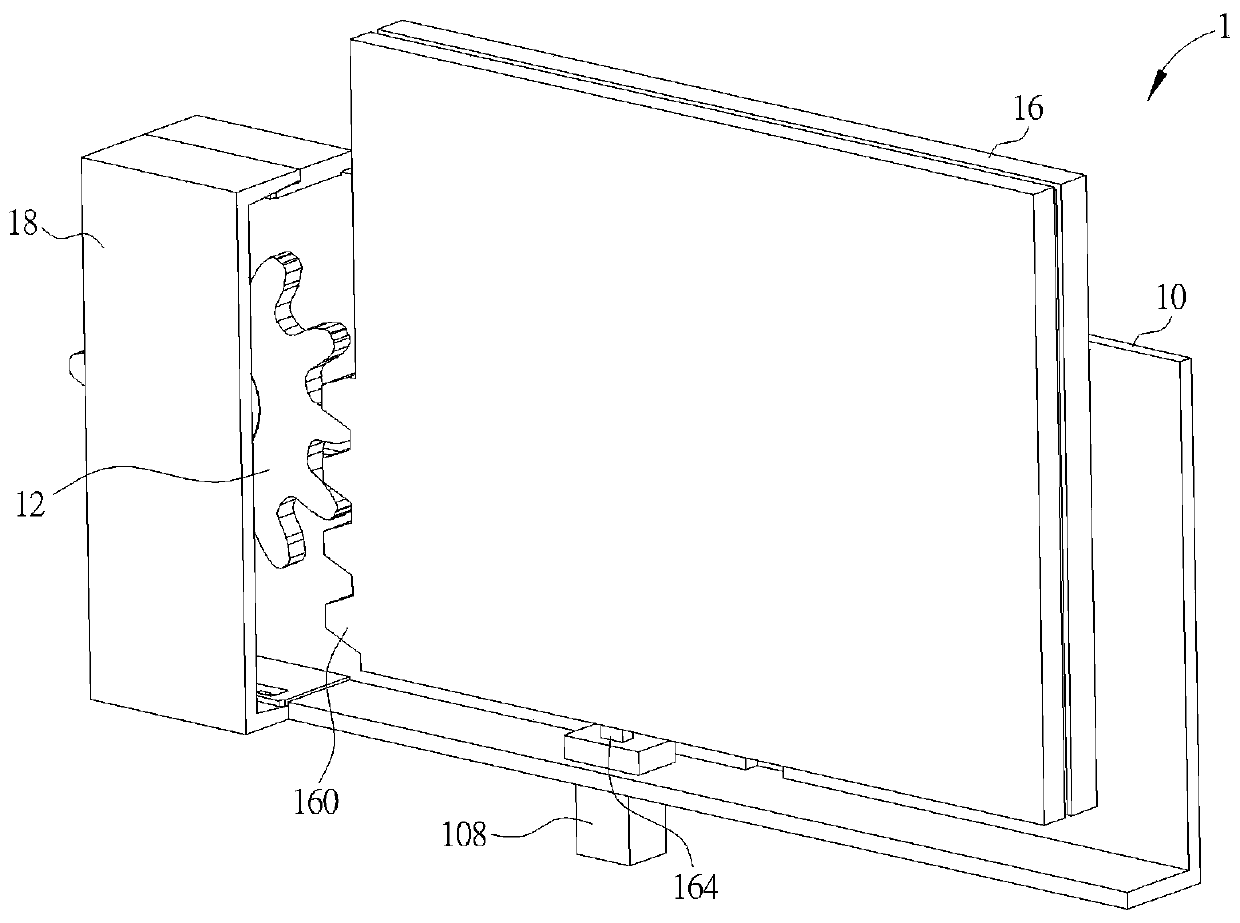
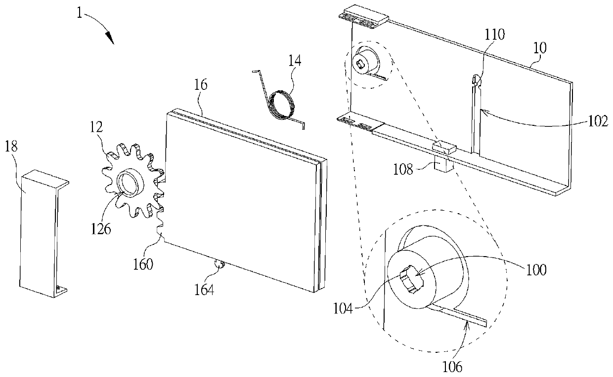
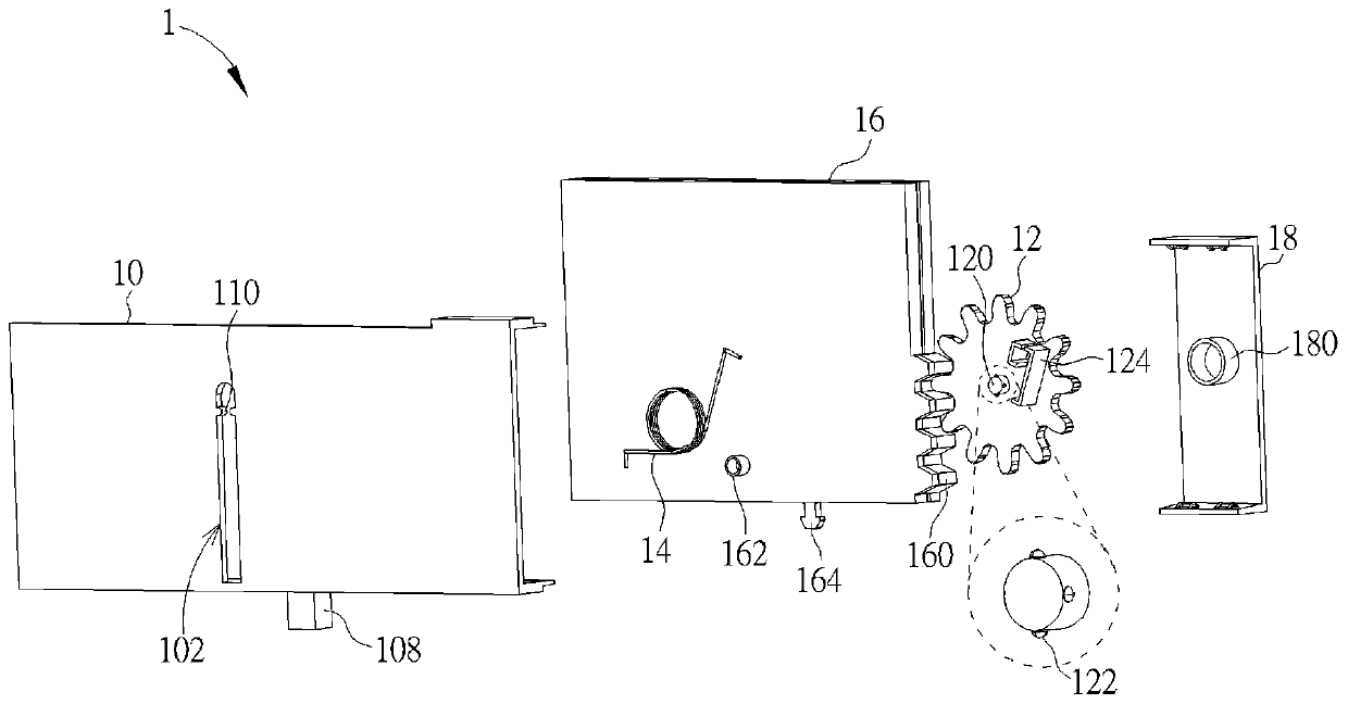
[0035] see Figure 1 to Figure 5 , figure 1 is a perspective view of a lifting device 1 according to an embodiment of the present invention, figure 2 for figure 1 Exploded diagram of lifting device 1 in, image 3 for figure 1 The explosion diagram of the lifting device 1 in another perspective, Figure 4 for figure 1 The front view of the lifting device 1 in, wherein the object 16 is in the first position relative to the base body 10, Figure 5 for Figure 4 A front view of the object 16 moving from the first position to the second position relative to the base body 10 .

[0036] Such as Figure 1 to Figure 5 As shown, the lifting device 1 includes a base body 10 , a gear 12 , a torsion spring 14 and an object 16 . In this embodiment, the base body 10 may b...


PUM


Abstract

The invention provides a lifting device which comprises a base, a gear, a torsional spring and an object. The base is provided with a shaft hole and one of a guide groove and a guide portion. The shaft hole is provided with a plurality of first interference portions. The gear is provided with a rotary shaft. The rotary shaft is rotatably arranged in the shaft hole. The rotary shaft is provided with a plurality of second interference portions arranged relative to the first interference portions. The two ends of the torsional spring are fixed to the base and the gear. The object is provided with a rack and the other one of the guide groove and the guide portion. The rack is engaged with the gear. When the object is located in a first position relative to the base, the torsional spring is in a compressed state. When the torsional spring is released from the compressed state, the torsional spring drives the gear to rotate, and the object is moved to a second position from the first position relative to the base. In the rotating process of the gear, the first interference portions and the second interference portions mutually generate friction interference. Thus, the object can move at a steady speed relative to the base.

Description

technical field [0001] The present invention relates to a lifting device, in particular to a lifting device capable of moving objects at a steady speed relative to a base. Background technique [0002] At present, some devices are equipped with a mechanism that can drive the object to move relative to the base, so as to move the object to different positions relative to the base according to the user's operation requirements. Please refer to US Patent Publication No. 6,247,203 (hereinafter referred to as the '203 patent), the '203 patent utilizes a strip-shaped compression spring as a compression element to automatically eject objects from the seat. However, when the compression spring ejects the object from the base, the speed of ejection cannot be controlled, and the object ejected instantly may sometimes frighten the user, or collide with surrounding objects and be damaged. Contents of the invention [0003] One object of the present invention is to provide an elevatin...

Claims


Application Information

Patent Timeline
Patent Type & Authority Patents(China)
IPC IPC(8): B66F11/00B66F13/00
CPCB66F11/00B66F13/00
Inventor 陈维凯
Owner QISDA SUZHOU
Learn More