Turbine engine

A technology of turbine engine and compressor, which is applied to engine components, machines/engines, gas turbine devices, etc., can solve the problem of reducing the combat radius and air time of the aircraft, further improving the temperature increase ratio and booster ratio, and difficult system thrust. Continue to increase and other problems to achieve the effect of reducing the overall structural quality, increasing the thrust-to-weight ratio, and improving the overall performance

Active Publication Date: 2017-05-31
清航空天(浙江)科技有限公司
View PDF4 Cites 6 Cited by
  • Summary
  • Abstract
  • Description
  • Claims
  • Application Information

AI Technical Summary

Problems solved by technology

Due to the limitations of the current material and technological level, it is difficult to further improve the cycle parameters such as the temperature increase ratio and boost ratio of the turbine-based propulsion method, which makes it difficult to continue to increase the thrust of the system. Although the use of afterburners and other methods can make the thrust of the engine The performance has been significantly improved, but the fuel consumption rate of the engine has been greatly increased, so that the combat radius and air time of the aircraft have been significantly reduced

Method used


Image

  • Turbine engine
  • Turbine engine
  • Turbine engine

Examples


Embodiment Construction

[0029] The turbine engine according to the present invention will be described in detail below with reference to the accompanying drawings.

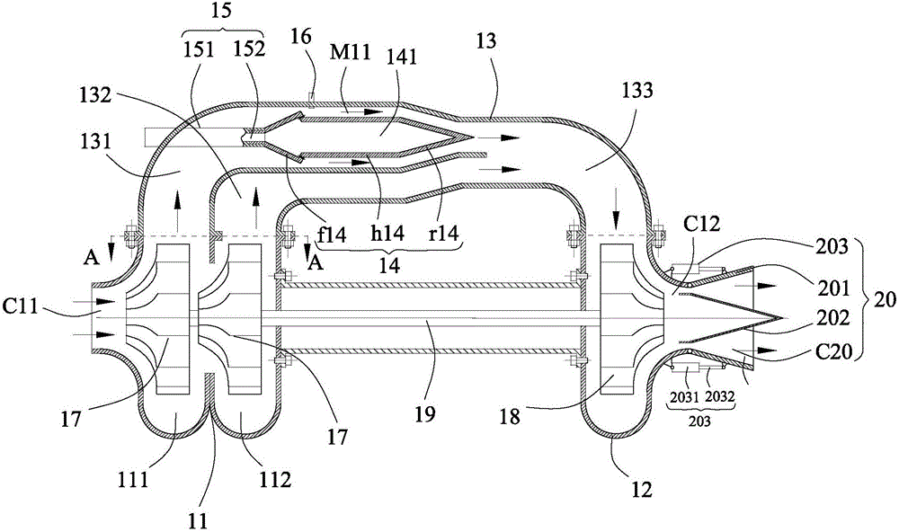
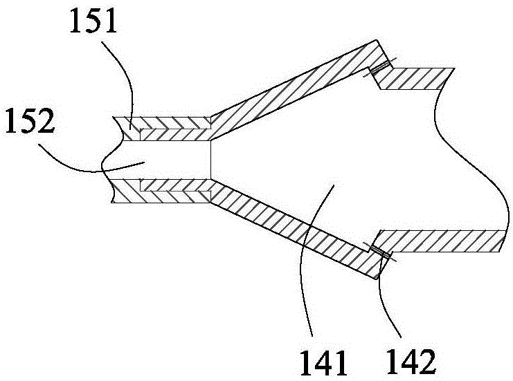
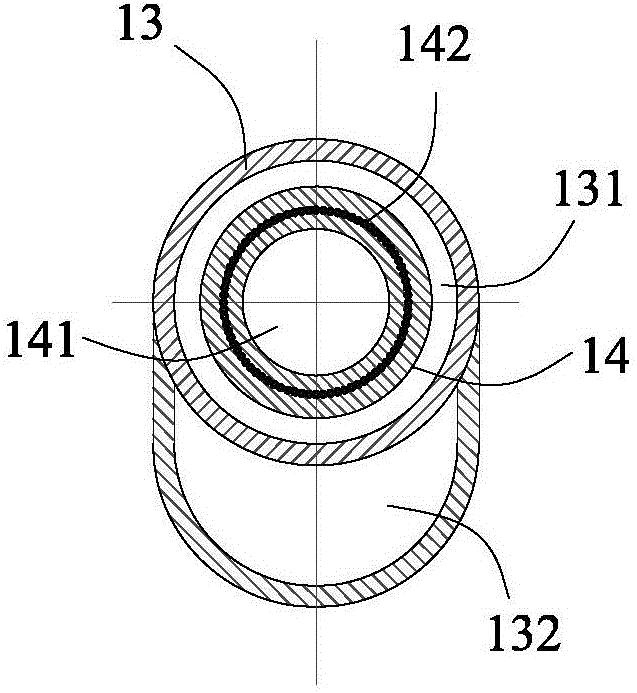
[0030] refer to Figure 1 to Figure 5 , according to the turbine engine of the present invention, comprising: a first housing 11, with an air inlet C11, and the air inlet C11 communicates with the outside atmosphere; a second housing 12, with an exhaust port C12; a third housing 13, fixedly connected to The first housing 11 and the second housing 12 are connected to the first housing 11 and the second housing 12; the central body 14 is arranged in the third housing 13, and the outer wall surface of the central body 14 is in contact with the third housing The inner wall of the body 13 forms a rotary detonation combustion chamber M11, which is connected to the air inlet C11 of the first housing 11 to receive external air; the oil circuit assembly 15 is controlled to communicate with the rotary detonation combustion chamber. chamber M11, t...


PUM


Abstract

The invention provides a turbine engine. The turbine engine comprises a first housing, a second housing, a third housing, a central body, an oil passage assembly, an igniter, a compressor, a turbo machine and a spindle. The first housing has an air inlet. The third housing is fixedly connected to the first housing and the second housing and communicates with the first housing and the second housing. The central body is arranged in the third housing. The outer wall surface of the central body and the inner wall surface of the third housing form a rotary detonation combustion chamber. The oil passage assembly communicates to the rotary detonation combustion chamber in a controllable manner. The igniter is used for igniting combustion gas which is formed by fuel and air entering the rotary detonation combustion chamber such that combustion gas rotates and combusts in a detonation manner. The compressor is used for compressing air entering the first housing through an air inlet. The turbo machine performs rotary motion under the drive of gas in the second housing. The spindle is used for connecting with the compressor and the turbo machine such that the turbo machine drives the compressor to perform motion. The turbine engine has following beneficial effects: the turbine engine is compact in structure and high in combustion efficiency; oil consumption rate of the engine is reduced; and the thrust-weight ratio and the overall performance of the engine are improved.

Description

technical field [0001] The invention relates to the technical field of engines, in particular to a turbine engine. Background technique [0002] Thrust-to-weight ratio (the ratio of thrust to engine weight) and fuel consumption rate are important indicators for measuring aviation gas turbine engines, which respectively determine the maneuverability and combat radius (or range) of the aircraft. Due to the limitations of the current material and technological level, it is difficult to further improve the cycle parameters such as the temperature increase ratio and boost ratio of the turbine-based propulsion method, which makes it difficult to continue to increase the thrust of the system. Although the use of afterburners and other methods can make the thrust of the engine The performance has been significantly improved, but the fuel consumption rate of the engine has been greatly increased, so that the combat radius and empty time of the aircraft have been significantly reduced...

Claims


Application Information

Patent Timeline
Patent Type & Authority Applications(China)
IPC IPC(8): F02K3/00F02K1/08F02C3/14F02C3/08F02C3/107F02C7/22F02C7/264
CPCF02C3/085F02C3/107F02C3/14F02C7/222F02C7/264F02K1/08F02K3/00
Inventor 计自飞王兵段瑞泽吴嘉奇张会强
Owner 清航空天(浙江)科技有限公司
Why Eureka
Try Eureka