
A pulsed strong magnetic field assisted laser welding method and equipment

A technology for assisting laser and welding methods, applied in laser welding equipment, welding equipment, metal processing equipment, etc., can solve the problems affecting the assembly accuracy of components and the overall performance of the structure, difficulty in welding thermal deformation control, and difficulty in operation, etc., to solve the joint problem. Effect of quality control and structural deformation, improving joint fatigue strength, and improving fatigue resistance

Active Publication Date: 2015-10-28
武汉飞能达激光技术有限公司
View PDF5 Cites 2 Cited by
  • Summary
  • Abstract
  • Description
  • Claims
  • Application Information

AI Technical Summary

Problems solved by technology

[0003] As a fusion welding process, the biggest problem faced by laser welding is the thermal deformation caused by heat input, which seriously affects the assembly accuracy of components and the overall performance of the structure, especially the fatigue performance, although its heat input and thermal influence are much smaller than traditional resistance Welding and Arc Welding Processes
Studies that have been carried out have shown that under laser welding conditions, the control of welding thermal deformation is often difficult
Traditional post-weld residual stress relief methods and orthopedic methods (such as hammering, mechanical vibration, post-weld slow cooling (aging method), heat treatment, etc.) are time-consuming and labor-intensive, and are difficult to operate offline welding stress relief methods, and the effect is not good

Method used


Image

  • A pulsed strong magnetic field assisted laser welding method and equipment
  • A pulsed strong magnetic field assisted laser welding method and equipment
  • A pulsed strong magnetic field assisted laser welding method and equipment

Examples


Embodiment 1

[0079] In this example, the laser spot welding process is implemented first, and then a pulsed strong magnetic field is applied to the spot welding seam area within a specific delay time just after the laser spot welding process is completed.

[0080] The welding workpiece in this example is a 2219 aluminum alloy cylindrical member with a plate thickness of 3mm. Figure 11 The pulsed strong magnetic field assisted laser spot welding equipment for cylindrical structural parts shown in the figure uses a 6000W fiber laser and a galvanometer scanning focusing method. The laser focal length is 400mm. The shape of the welding spot of the weld seam is a solid circle, and the cross-sectional feature is an unpenetrated form. . In order to improve the quality of the weld seam, a 0.1mm thick rare earth film is preset on the surface of the workpiece.

[0081] The process parameters of laser spot welding are: laser power 4500W, laser spot diameter 1.5mm, single spot welding time 0.2s, las...

Embodiment 2

[0084] The workpiece to be welded in this example is an MB8 magnesium alloy plate member with a plate thickness of 2.5mm, a length of 2m, and a width of 1m. Figure 12 The pulsed strong magnetic field assisted laser spot welding equipment for flat structural parts shown in the figure uses fiber laser and galvanometer scanning focusing mode. The laser focal length is 300mm. The shape of the welding spot of the weld seam is a solid circle, and the cross-sectional feature is an incomplete form.

[0085] The process parameters of the laser spot welding process are: laser power 2500W, laser spot diameter 0.5mm, single spot welding time 3s, laser beam swing along the radial direction 5mm. The process parameters of the pulsed magnetic field applied after laser spot welding are: a specific delay time after spot welding is 60s, the distance between the electromagnetic conversion device and the workpiece surface is 8mm, the induction intensity of the pulsed magnetic field is 15T, and the...

Embodiment 3

[0088] In this example, the welding workpiece is a TC4 titanium alloy plate structure with a plate thickness of 5 mm. The welding requirement is butt spot welding. DISK solid-state laser and vibrating mirror scanning focusing method are selected, and the laser focal length is 250 mm. The shape of the weld spot of the weld is a solid circle, and the cross-sectional feature is a full penetration form.

[0089]The process parameters of the laser spot welding process are: laser power 3500W, laser spot diameter 0.8mm, single spot welding time 1s, laser beam swing along the radial direction 2mm. The process parameters of the pulsed strong magnetic field applied after laser spot welding are: a specific delay time after spot welding is 300s, the distance between the electromagnetic conversion device and the workpiece surface is 5mm, the induction intensity of the pulsed magnetic field is 20T, and the magnetic field pulse width is 30μs.

[0090] After the welding is completed, there ar...


PUM

PropertyMeasurementUnit
diameteraaaaaaaaaa
diameteraaaaaaaaaa
fatigue strengthaaaaaaaaaa

Abstract

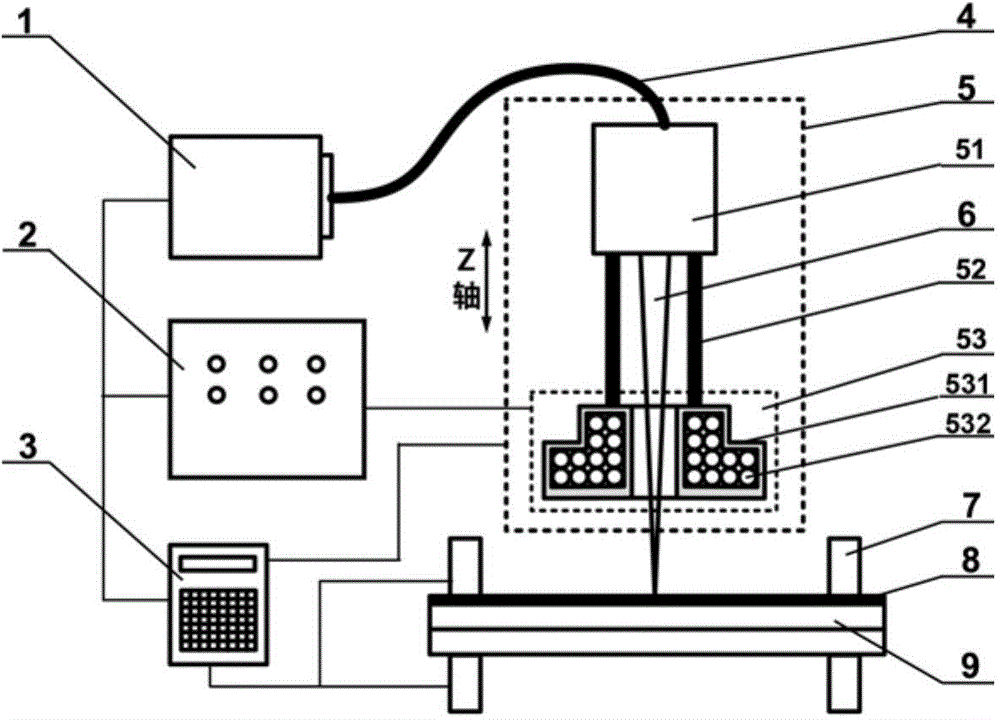
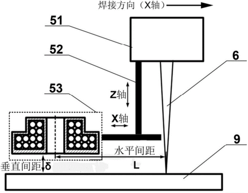
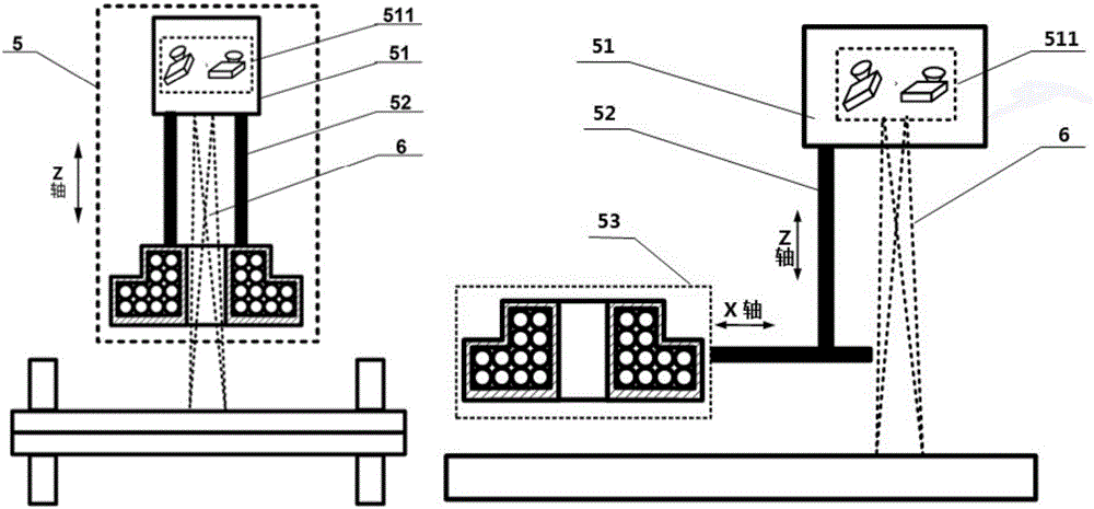
The invention discloses a pulsed high magnetic field auxiliary laser welding method and device. The method and device can be applied to laser spot welding and seam welding. According to the method, in the overall welding process, laser beams are emitted to a workpiece to form a welding connector, a high pulsed magnetic field is exerted to the welding connector which is just solidified and the surrounding area, the pulsed magnetic field generates pressure stress on the surface of the workpiece to enable the connector area to have plastic deformation, residual stress is released to lower the degree of stress concentration and the degree of structural deformation of the welding connector, and the fatigue strength of the welding connector is improved. The device comprises a laser, a pulsed magnetic field generator, a numerical control system, an optical transmission system and a laser pulsed magnetic field composite processing head. The processing head is used for integrating the laser beams and the high pulsed magnetic field, and regulating the perpendicular distance between an electromagnetic conversion device and the surface of the workpiece and the horizontal distance between the electromagnetic conversion device and the laser beams. By means of the pulsed high magnetic field auxiliary laser welding method and device, structural deformation can be lowered, welding quality and processing efficiency are improved, and the processing effect which is superior to that of an existing laser welding process is achieved.

Description

technical field [0001] The invention belongs to welding technology, and in particular relates to a pulsed strong magnetic field assisted laser welding method and equipment, and is especially suitable for pulsed strong magnetic field assisted laser welding of metal material thin-walled structures. Background technique [0002] Welding is an important processing method for structural parts of metal materials, and it is widely used in manufacturing fields such as vehicles, aerospace, ships, buildings, bridges, and pressure vessels. Laser welding technology uses a laser with high energy density as a heat source to heat and melt the workpiece to carry out welding. It has fast welding speed, small deformation, good joint quality, small heat-affected zone, and is suitable for various metal materials. It is easy to realize automation. A series of advantages are the focus of the current development of advanced manufacturing technology. For example, Airbus A318, A340 and A380 adopt l...

Claims


Application Information

Patent Timeline
Patent Type & Authority Patents(China)
IPC IPC(8): B23K26/20B23K26/22B23K26/70
CPCB23K26/22B23K26/24B23K26/702
Inventor 曾晓雁高明王磊李耿张臣王泽敏李祥友
Owner 武汉飞能达激光技术有限公司
Learn More