High-pressure fuel pipe for diesel engines

a fuel pipe and high-pressure technology, applied in the direction of hose connections, machines/engines, branching pipes, etc., can solve the problems of minute wrinkle cracks, inner winkles, wrinkle cracks, etc., and achieve high inner-pressure fatigue strength, high plastic deformation, and enhanced tensile strength

Inactive Publication Date: 2005-06-16
USUI KOKUSAI SANGYO KAISHA LTD
View PDF6 Cites 29 Cited by
  • Summary
  • Abstract
  • Description
  • Claims
  • Application Information

AI Technical Summary

Benefits of technology

[0011] The invention has been thought of in order to solve the problem of the prior art described above and has its object to provide a high-pressure fuel pipe for diesel engines, which is excellent in inner-pressure fatigue resistant property, vibrational fatigue resistant property, cavitation-resistant property, and also excellent in seat surface crack resistant property, and bending shape stability, and capable of thinning and lightening.
[0015] Also, the reason why plastic working is applied to an inner surface of a flow passage is that by inducing martensite transformation, tensile strength is further enhanced to provide a high inner-pressure fatigue strength.
[0016] A high-pressure fuel pipe for diesel engines, according to the invention, is high in plastic deformability and is made of a low alloy transformation inducing plastic type strength steel, which makes a martensite structure by virtue of plastic working and is high in both strength and hardness, so that an entire pipe is high in strength and hardness, excellent in inner-pressure fatigue resistant property, vibrational fatigue resistant property, cavitation-resistant property, seat surface crack resistant property, and bending shape stability, and capable of thinning and lightening.
[0017] Also, a pipe has good workability in the course of working and has an inner surface, which is smooth (free of crack). Further, since reduction at the time of pipe elongation is made large, there is produced an effect that the number of times of pipe elongation can be reduced and working with the same reduction can be performed with a small pipe elongation machine and a small die.

Problems solved by technology

Such high tensile strength pipes cause, in some cases, minute wrinkle cracks (defect) having a depth of the order of 100 μm on an inner surface when manufactured from an ingot in hot pipe-making, and when worked to a necessary size from a large-diameter pipe in drawing (pipe elongation).
It is known that such wrinkle cracks are caused by that difference in material flow between outside and inside, which is generated when a pipe is reduced in outside diameter by a die and rolled from inside by a plug in pipe elongation working.
Also, inner winkles caused by rolling with the plug remain as wrinkle cracks due to small ductility.
In particular, when wrinkle cracks of the order of 100 μm are present on a pipe inner surface, fatigue failure occurs due to stress concentration generated on the wrinkle crack portion when high inner pressure of 1200 to 1600 bar is repeatedly applied in a pipe.
While the specific cutting technique can be used to remove a defect on the inner peripheral surface, which defines a starting point to give rise to inner-pressure fatigue failure, and to increase the inner-pressure fatigue strength, however, it is not possible to endure pressures of the order of 1800 bar or higher due to a limit in material strength.
With this method, however, distribution of residual stress changes due to subsequent plastic deformation and disappears.
Also, in case of generating a compression residual stress on an inner surface, the inner surface is susceptible of work hardening but a normal work hardening of a material makes inner-surface fatigue strength insufficient.
While vibrational fatigue advances with an outer surface of a pipe as a main starting point, the outer surface is not absolutely increased in strength, so that the vibrational fatigue property is in no way improved.
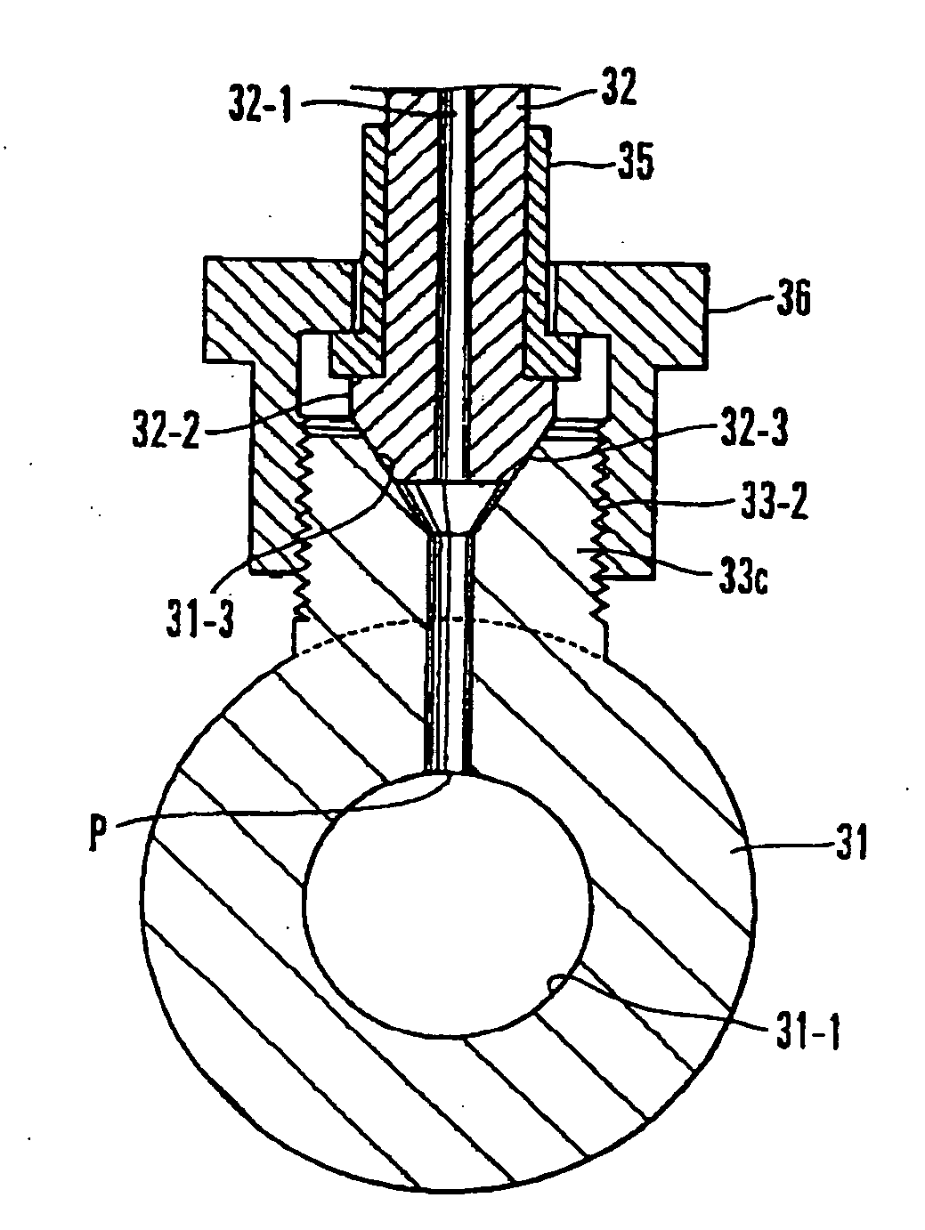
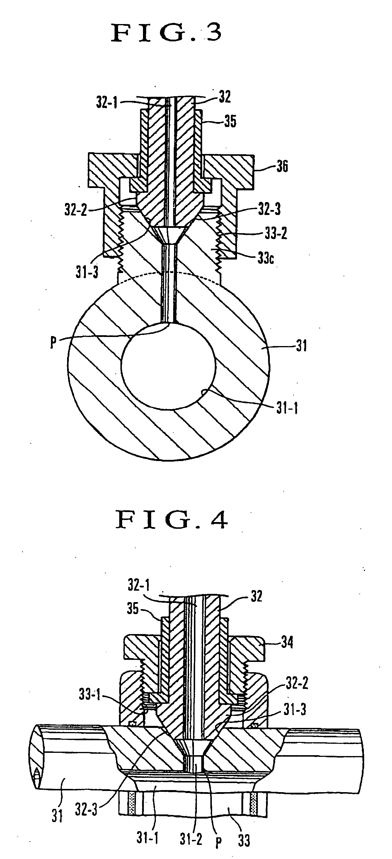
However, all the prior common rails described above involve the possibility that a large stress is generated on an inner peripheral edge P of a lower end of the branch hole 31-2 by internal pressure in the main pipe rail 31 and an axial force applied on the pressure receiving surface 31-3 by push of the connection head 32-2 of a branch connecting body such as the branch pipe 32, and crack is liable to generate with the inner peripheral edge P as a starting point to give rise to leakage of a fuel.
Also, crack is liable to generate on an inner surface of the main pipe rail.

Method used


Image

  • High-pressure fuel pipe for diesel engines
  • High-pressure fuel pipe for diesel engines
  • High-pressure fuel pipe for diesel engines

Examples


embodiment 1

[0033] A seamless steel pipe (mother pipe) made of A steel containing components shown in TABLE 1 and sized to have an outside diameter of 34 mm, a wall thickness of 4.5 mm, and an inside diameter of 25 mm was used to be repeatedly subjected to predetermined pipe elongation and annealing, austenitized at 950° C. for 12 minutes, thereafter subjected to austempering treatment to be held at 450° C. for 5 minutes (volume fraction of residual austenite being 5.0%), and thereafter subjected to final pipe elongation working to provide a TB steel pipe, product size of which includes an outside diameter of 8 mm, a wall thickness of 2 mm, and an inside diameter of 4 mm, and forming of a joint portion thereof and bending were carried out to provide a product without annealing in product size.

embodiment 2

[0034] A seamless steel pipe (mother pipe) made of A steel containing components shown in TABLE 1 and sized to have an outside diameter of 34 mm, a wall thickness of 4.5 mm, and an inside diameter of 25 mm was used to be repeatedly subjected to predetermined pipe elongation and annealing, and thereafter subjected to final pipe elongation working to provide a TB steel pipe having a product size including an outside diameter of 8 mm, a wall thickness of 2 mm, and an inside diameter of 4 mm, the TB steel pipe thus obtained was austenitized at 950° C. for 12 minutes, and thereafter subjected to austempering treatment to be held at 425° C. for 5 minutes (volume fraction of residual austenite being 11.2%), and thereafter forming of a joint portion thereof, bending, and autofrettage working (inner pressure, at which a portion from an inner surface to a region corresponding to a wall thickness of 50% yielded) were carried out in product size.

embodiment 3

[0035] A seamless steel pipe (mother pipe) made of A steel containing components shown in TABLE 1 and sized to have an outside diameter of 34 mm, a wall thickness of 4.5 mm, and an inside diameter of 25 mm was used to be repeatedly subjected to predetermined pipe elongation and annealing, and thereafter subjected to final pipe elongation working to provide a TB steel pipe, product size of which includes an outside diameter of 8 mm, a wall thickness of 2 mm, and an inside diameter of 4 mm, the TB steel pipe thus obtained was austenitized at 780° C. for 12 minutes, thereafter subjected to austempering treatment to be held at 400° C. for 10 minutes (volume fraction of residual austenite being 13.7%), and subjected to rustproofing after cooling, and thereafter forming of a joint portion thereof and bending were carried out in product size to provide a product.


PUM

PropertyMeasurementUnit
crack depthaaaaaaaaaa
tensile strengthaaaaaaaaaa

Abstract

There is provided a high-pressure fuel pipe for diesel engines, which is excellent in inner-pressure fatigue resistant property, vibrational fatigue resistant property, cavitation-resistant property, seat surface crack resistant property, and bending shape stability, and capable of thinning and lightening. A high-pressure fuel pipe for diesel engines, composed of a low alloy transformation inducing plastic type strength steel containing residual austenite of 5 to 40 wt %, and wherein an inner surface of a flow passage has a crack depth of 20 μm or less, and plastic working is applied to an inner surface of a flow passage.

Description

BACKGROUND OF THE INVENTION [0001] 1. Field of the Invention [0002] The present invention relates to a high-pressure fuel pipe for internal combustion diesel engines (including a common rail, feed pipe for common rail, and fuel injection pipe). [0003] 2. Background Art [0004] Known as a fuel injection pipe among high-pressure fuel pipes for diesel engines are ones, in which a frustum-shaped connection head 12 having a straight-shaped seat surface 13 defined on an outer peripheral surface of an end of a thick-walled steel pipe 11 shown in FIG. 1, or a connection head 22 having an arcuate-shaped seat surface 23 defined on an outer peripheral surface of an end of a thick-walled steel pipe 21 shown in FIG. 2 is formed by buckling working performed by push from outside by a punch member in an axial direction (see JP-A-2002-295336). [0005] Generally, a steel pipe (STS370, 410 of JISG3455) having a tensile strength of the class of 340 N / mm2 to 410 N / mm2 has been used for such fuel injectio...

Claims


Application Information

Patent Timeline
Patent Type & Authority Applications(United States)
IPC IPC(8): F02M55/02F02M61/16F16L9/02
CPCF02M55/025F02M55/02
Inventor USUI, MASAYOSHIASADA, KIKUOTAKAHASHI, TERUHISA
Owner USUI KOKUSAI SANGYO KAISHA LTD
Why Eureka
Try Eureka