Modular directional flow pipeline type piezoelectric energy harvester arranged in a circumferential array

A technology of array arrangement and piezoelectric energy harvesting, applied in the direction of piezoelectric effect/electrostrictive or magnetostrictive motors, electrical components, generators/motors, etc., can solve the problem of large application limitations and difficult adjustment of coupling relationship and other problems, to achieve the effect of high space utilization, increased vibration amplitude, and novel structure

Active Publication Date: 2019-10-25
HARBIN INST OF TECH
View PDF4 Cites 2 Cited by
  • Summary
  • Abstract
  • Description
  • Claims
  • Application Information

AI Technical Summary

Problems solved by technology

[0004] The purpose of the present invention is to provide a piezoelectric energy harvester arranged in a circumferential array of modular directional flow pipelines, to solve the problem that most of the energy harvesters in the existing flow-induced vibration energy harvesting are fixed and the coupling relationship between them Difficult to adjust and large application limitations

Method used


Image

  • Modular directional flow pipeline type piezoelectric energy harvester arranged in a circumferential array
  • Modular directional flow pipeline type piezoelectric energy harvester arranged in a circumferential array
  • Modular directional flow pipeline type piezoelectric energy harvester arranged in a circumferential array

Examples


Embodiment Construction

[0030] Preferred embodiments of the present invention will be described in detail below with reference to the accompanying drawings.

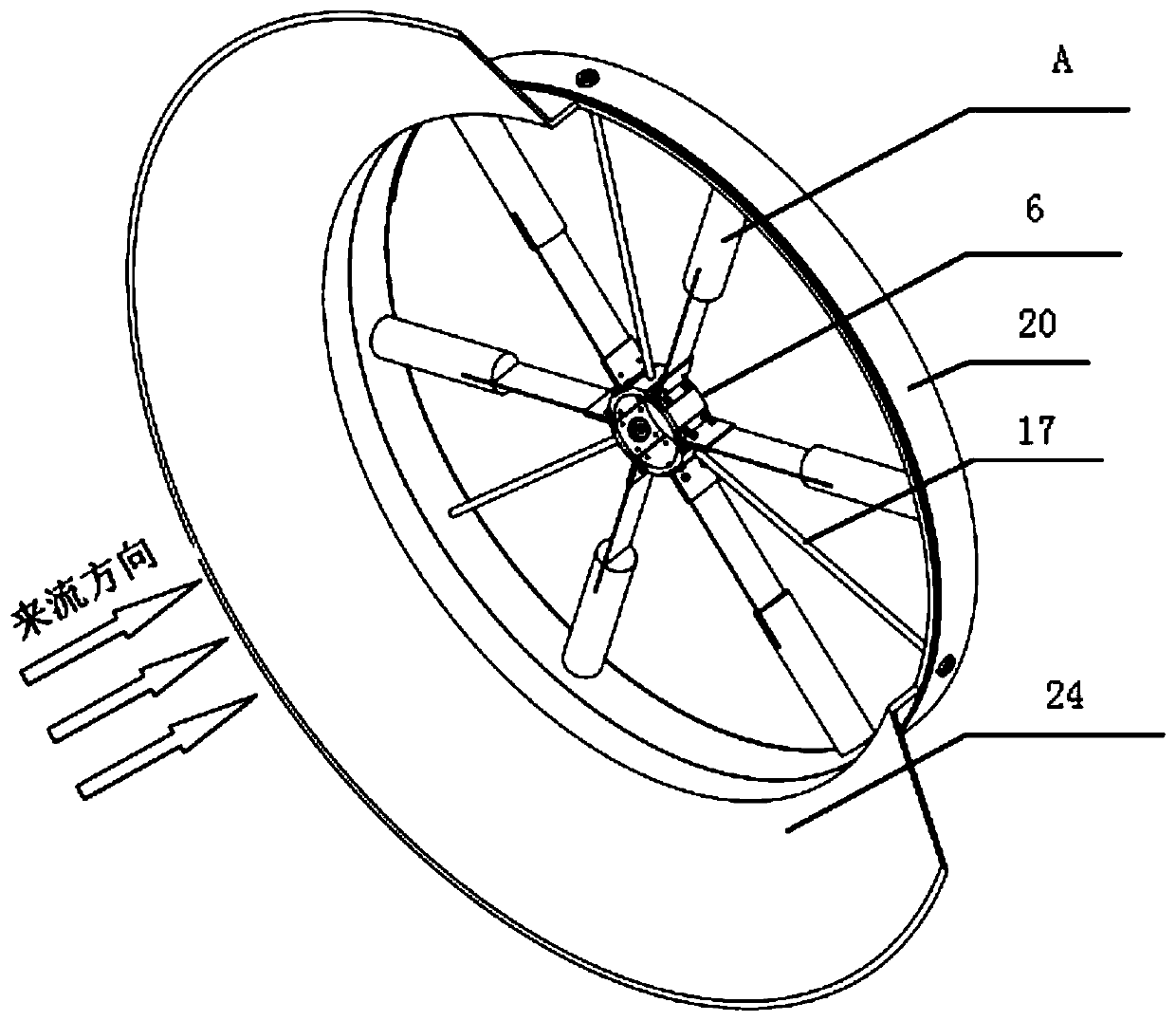
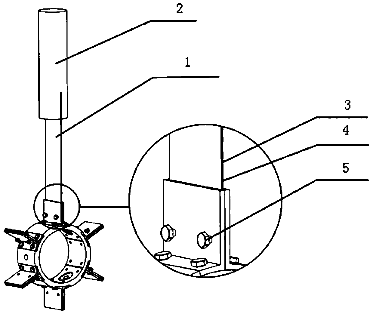
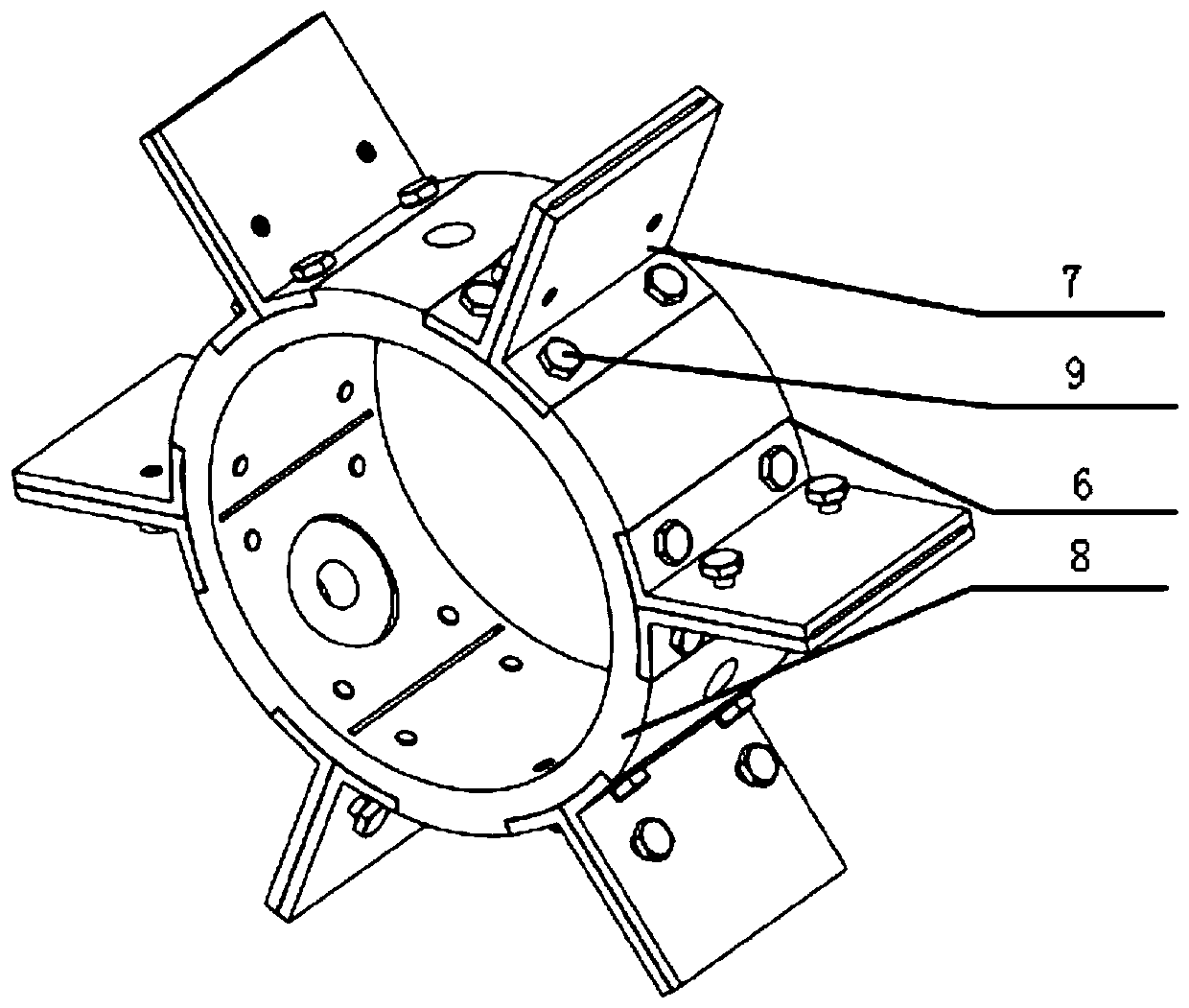
[0031] Such as Figure 1 to Figure 13 As shown, a piezoelectric energy harvester arranged in a modular directional flow pipe circumferential array described in this embodiment includes a piezoelectric vibrator, a central support, a current-limiting outer ring, a connecting screw, and a flow-concentrating speed increaser. ring; the piezoelectric vibrator includes a piezoelectric cantilever beam 1 and a spoiler column 2; the piezoelectric cantilever beam 1 is formed by attaching a piezoelectric material 3 to an elastic base 4, both of which have the same width, and are inserted into a central support 6 On the top, it is clamped by the clamping plates 7 on both sides, and fixed by pressing the compression bolts 5 through the threaded holes 10 on the side, and there are 6 pieces evenly distributed in the circumferential direction. The seat 8 and t...


PUM


Abstract

The invention relates to a modular directional flow pipeline type piezoelectric energy harvester arranged in a circumferential array, which belongs to the technical field of water flow and air flow induced vibration energy harvesting and solves the problems that energy harvesters in the existing flow-induced energy harvesting are mostly fixed, the mutual coupling relation is difficult to adjust and that the application limitation is large. The piezoelectric energy harvester comprises a flow-gathering and speed-accelerating coil and at least one piezoelectric module, the piezoelectric modules are connected in series when there are two or more piezoelectric modules, each piezoelectric module includes a plurality of piezoelectric vibrators, a central support, a current-limiting outer ring andconnecting screws; the central support and the current-limiting outer ring are coaxially arranged inside and outside and are connected through a plurality of connecting screws, and the plurality of piezoelectric vibrators are arranged in a circumferential array between the central support and the current-limiting outer ring; the flow-gathering and speed-accelerating ring is coaxially arranged onthe outer end face of the current-limiting outer ring on the incoming side; and a plurality of long holes are formed in the central support along the circumferential direction of the central support.The piezoelectric energy harvester can be widely applied to energy collection in the fields of stream pipelines, distillation pipelines, tap water pipelines, exhaust pipelines and the like.

Description

technical field [0001] The invention relates to a piezoelectric energy harvester, in particular to a piezoelectric energy harvester arranged in a circumferential array of modular directional flow pipelines, and belongs to the technical field of vibration energy harvesting caused by water flow and air flow. Background technique [0002] Flow-induced vibration energy capture is a technology that uses the vortex induced force generated by the alternately shedding vortices to excite the vibration of the energy-harvesting vibrator when the water flow or air flow passes through the non-streamlined object, thereby generating electric energy. [0003] Most of the flow-induced vibration energy harvesters in the prior art are single or series-parallel energy harvesters, and the space utilization rate needs to be developed, and it is difficult to reach the resonance frequency of the energy harvester in the face of low-speed fluid, thereby affecting the output. Studies have shown that t...

Claims


Application Information

Patent Timeline
Patent Type & Authority Applications(China)
IPC IPC(8): H02N2/18
CPCH02N2/185
Inventor 单小彪冯雎谢涛
Owner HARBIN INST OF TECH
Why Eureka
Try Eureka