Immunoassay device with immuno-reference electrode

a technology of immunoreference and immunoassay, which is applied in the direction of biomass after-treatment, instrumentation, suspension, etc., can solve the problems of variability of fluid test parameters from cartridge to cartridge, increase the cost of analysis of laboratory testing, and adverse to the condition or prognosis of patients, so as to increase the ionic strength of the sample and reduce interference

Inactive Publication Date: 2010-05-25
ABBOTT POINT CARE
View PDF49 Cites 231 Cited by
  • Summary
  • Abstract
  • Description
  • Claims
  • Application Information

AI Technical Summary

Benefits of technology

[0027]providing a conduit for receiving a whole-blood sample in an immunoassay device, said conduit containing a salt reagent and means for treating the sample sufficient to increase the ionic strength of the sample and thereby reduce interference from the buffy coat when the sample contacts the immunosensor.
[0029]adding a salt reagent to a whole-blood sample for an immunoassay device to increase the ionic strength of the sample and thereby reduce interference from the buffy coat when the sample contacts the immunosensor.

Problems solved by technology

Laboratory testing increases the cost of analysis and delays the results.
In many circumstances, delay can be detrimental to a patient's condition or prognosis, such as for example the analysis of markers indicating myocardial infarction.
A potential problem with such disposable devices is variability of fluid test parameters from cartridge to cartridge due to manufacturing tolerances or machine wear.
There is no anticipation of the use of a bulk conductivity sensor and an immunosensor, or making the measurements in undiluted blood.
However, these do not disclose a sealing element that is slidably movable over at least a portion of a planar surface to displace excess fluid away from a sample entry port, so as to seal a volume of fluid within a holding chamber and inhibit the fluid from prematurely breaking through a capillary stop.

Method used


Image

  • Immunoassay device with immuno-reference electrode
  • Immunoassay device with immuno-reference electrode
  • Immunoassay device with immuno-reference electrode

Examples


example 1

[0180]Referring now to FIG. 7, which illustrates the principle of an amperometric immunoassay according to specific embodiments of the present invention for determination of troponin I (TnI), a marker of cardiac function. A blood sample, for example, is introduced into the sample holding chamber of a cartridge of the present invention, and is amended by a conjugate molecule comprising alkaline phosphatase enzyme (AP) covalently attached to a polyclonal anti-troponin I antibody (aTnI) 71. This conjugate specifically binds to the TnI, 70, in the blood sample, producing a complex made up of TnI bound to the AP-aTnI conjugate. In a capture step, this complex binds to the capture aTnI antibody 72 attached on, or close to, the immunosensor. The sensor chip has a conductivity sensor which is used to monitor when the sample reaches the sensor chip. The time of arrival of the fluid can be used to detect leaks within the cartridge: a delay in arrival signals a leak. The position of the sample...

example 2

Method of Use of a Cartridge

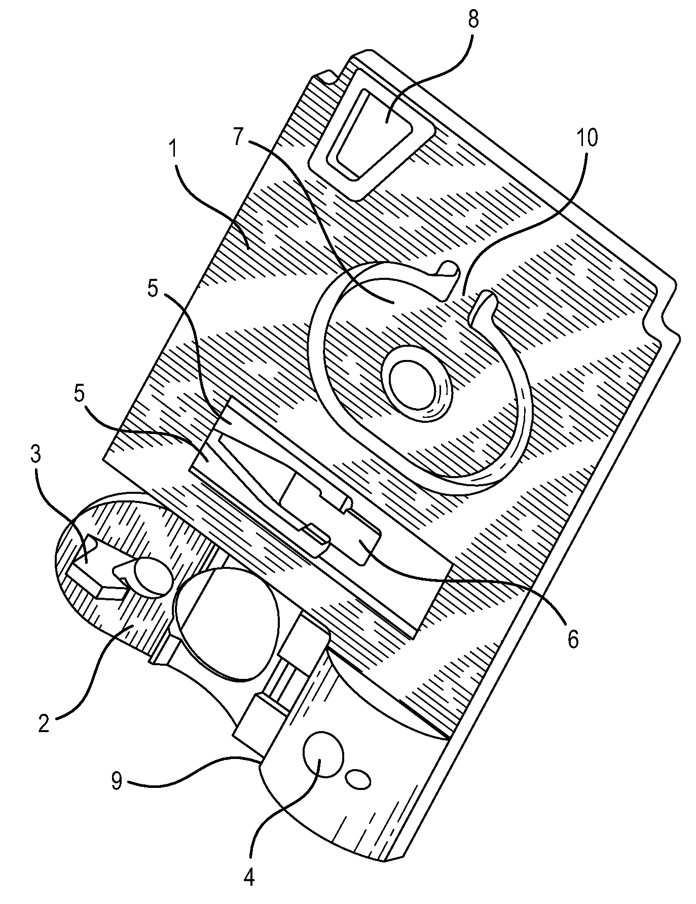
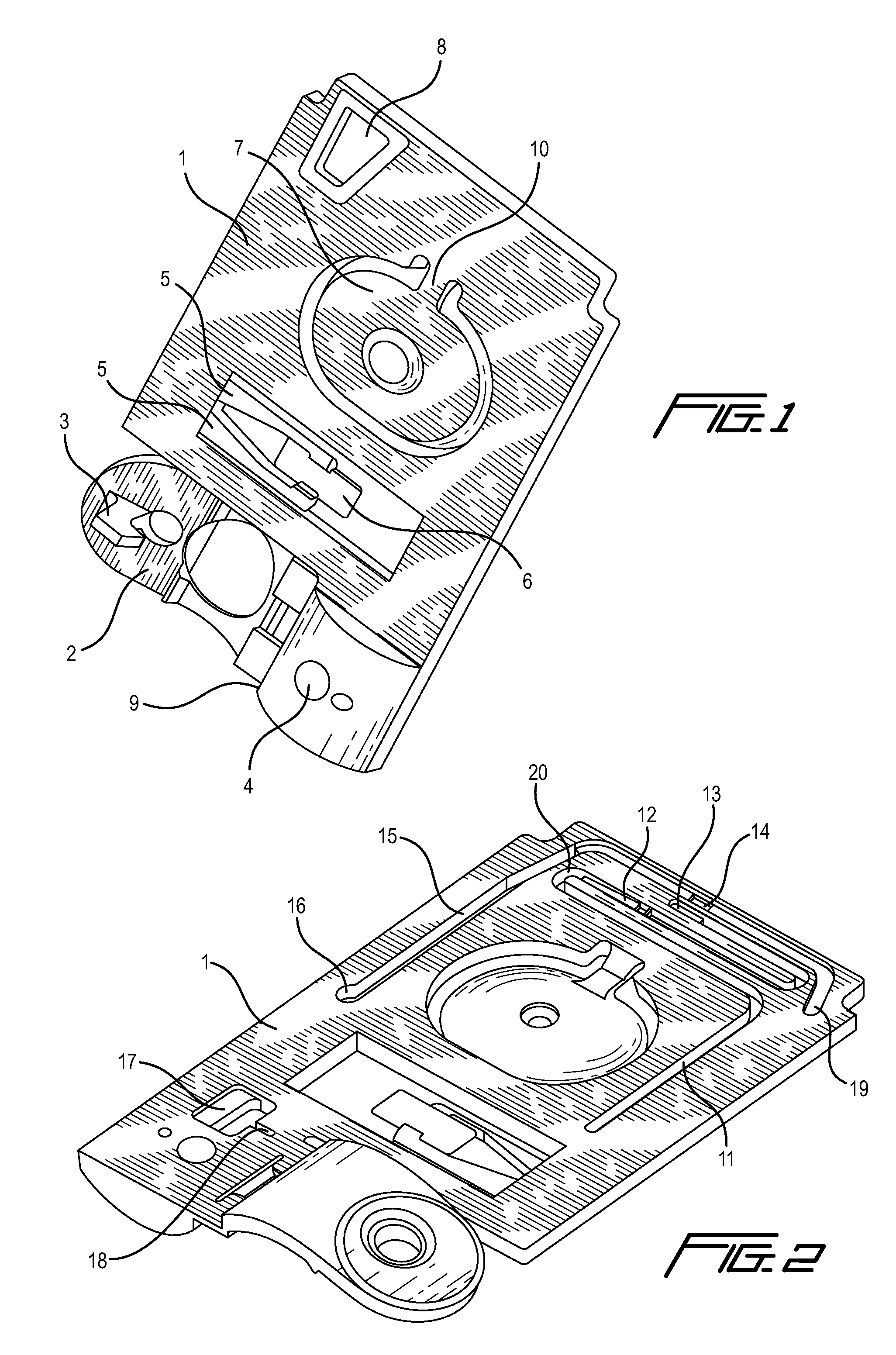
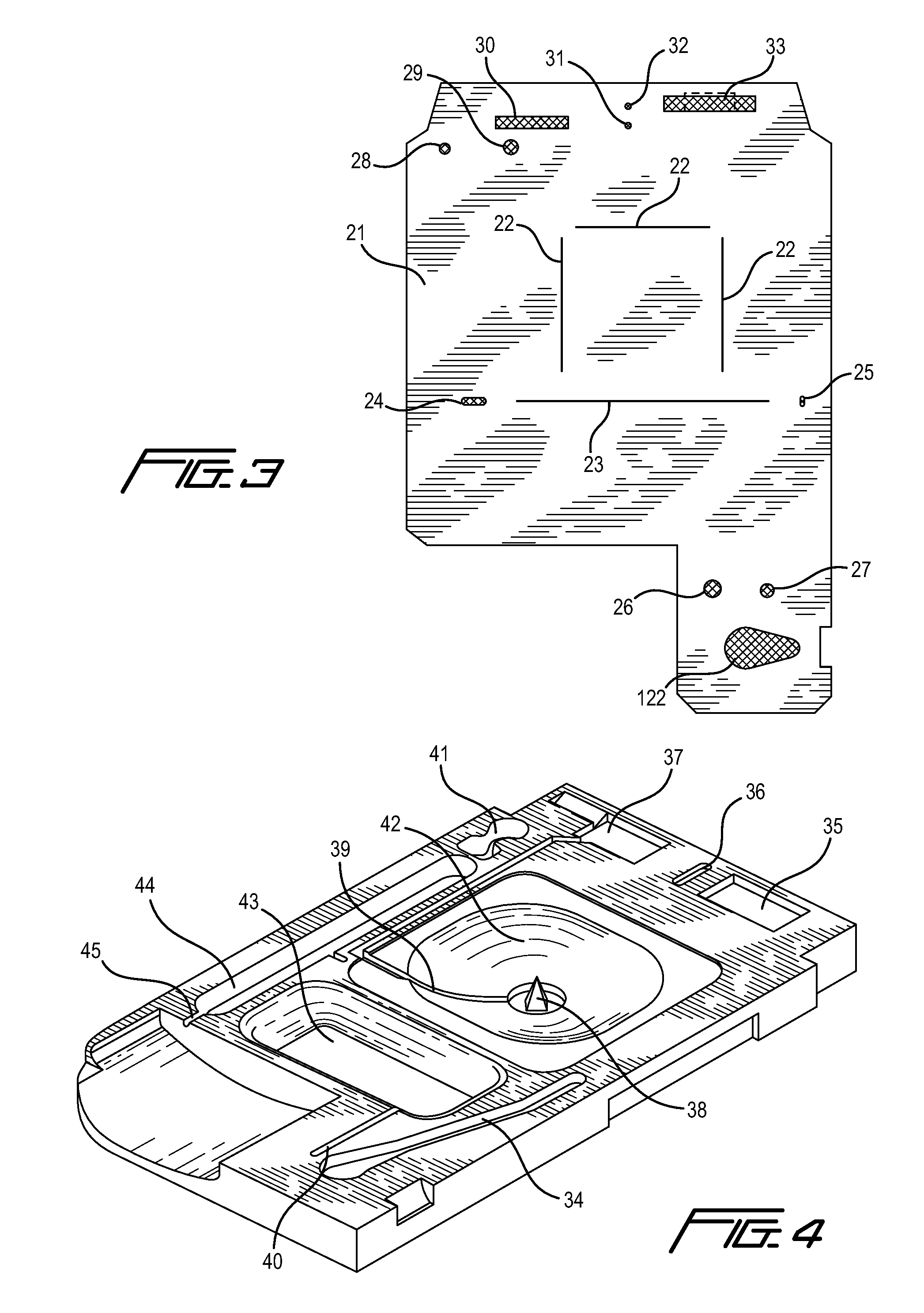
[0199]An unmetered fluid sample is introduced into sample chamber 34 of a cartridge according to claim 1, through sample entry port 4. Capillary stop 25 prevents passage of the sample into conduit 11 at this stage, and conduit 34 is filled with the sample. Lid 2 or element 200 is closed to prevent leakage of the sample from the cartridge. The cartridge is then inserted into a reading apparatus, such as that disclosed in U.S. Pat. No. 5,821,399 to Zelin, which is hereby incorporated by reference. Insertion of the cartridge into a reading apparatus activates the mechanism which punctures a fluid-containing package located at 42 when the package is pressed against spike 38. Fluid is thereby expelled into the second conduit, arriving in sequence at 39, 20, 12 and 11. The constriction at 12 prevents further movement of fluid because residual hydrostatic pressure is dissipated by the flow of fluid via second conduit portion 11 into the waste chamber 44. In a se...

example 3

Method of Use of a Cartridge

[0208]Use of a cartridge with a closeable valve, preferably located between the sensor chamber and the waste chamber, is herein illustrated by a specific embodiment in which the concentration of HCG is determined within a blood sample, which is introduced into the sample chamber of said cartridge. In the following time sequence, time zero (t=0) represents the time at which the cartridge is inserted into the cartridge reading device. Times are given in minutes. Between t=0 and t=1.5, the cartridge reading device makes electrical contact with the sensors through pads 91, 93, 95, and 97, and performs certain diagnostic tests. Insertion of the cartridge perforates the foil pouch introducing fluid into the second conduit as previously described. The diagnostic tests determine whether fluid or sample is present in the conduits using the conductivity electrodes; determine whether electrical short circuits are present in the electrodes; and ensure that the sensor...


PUM

PropertyMeasurementUnit
diameteraaaaaaaaaa
diameteraaaaaaaaaa
diameteraaaaaaaaaa

Abstract

An electrochemical immunosensor system with reduced interference, comprising: a first immunosensor that generates an electrochemical signal based on the formation of a sandwich between an immobilized antibody, a target analyte and a labeled antibody, wherein a portion of the signal arises from non-specific binding of the labeled antibody in the region of the first immunosensor, anda second immunosensor that acts as an immuno-reference sensor and generates a signal that is the same as or predictably related to the degree of non-specific binding which occurs in the region of the first immunosensor, and has an immunocomplex between an immobilized antibody and an endogenous or exogenous protein that is in the sample and that is not the target analyte.

Description

I. FIELD OF THE INVENTION[0001]An apparatus and method for rapid in situ determination of analytes in liquid samples that is capable of being used in the point-of-care clinical diagnostic field, including use at accident sites, emergency rooms, in surgery, in intensive care units, and also in non-medical environments.II. BACKGROUND OF THE INVENTION[0002]The invention relates to an apparatus and its method of use for determining the presence or concentrations of analytes in a liquid sample with single-use disposable cartridges adapted for conducting diverse real-time or near real-time assays of analytes.[0003]In specific embodiments, the invention relates to the determination of analytes in biological samples such as blood using electrochemical immunosensors or other ligand / ligand receptor-based biosensors. The invention further relates to a reference-immunosensor for use with an immunosensor to reduce the effect of interferences in an immunoassay, it also relates to reducing the eff...

Claims


Application Information

Patent Timeline
Patent Type & Authority Patents(United States)
IPC IPC(8): C12M1/34C12M3/00G01NG01N27/00G01N33/53G01N33/537G01N33/543
CPCG01N33/5438Y10T436/25Y10S436/807
Inventor MILLER, CARY JAMESCAMPBELL, JOHN LEWIS EMERSON
Owner ABBOTT POINT CARE
Why Eureka
Try Eureka