
Methods and apparatus for use in a wireless communications system that uses a multi-mode base station

a wireless communications system and multi-mode technology, applied in the direction of power management, synchronisation arrangement, high-level techniques, etc., can solve the problems of adverse effects and waste of base station power, and achieve the effects of reducing base station transmissions, and reducing interference with communications in neighboring cells

Active Publication Date: 2007-03-22
QUALCOMM INC
View PDF8 Cites 227 Cited by
  • Summary
  • Abstract
  • Description
  • Claims
  • Application Information

AI Technical Summary

Benefits of technology

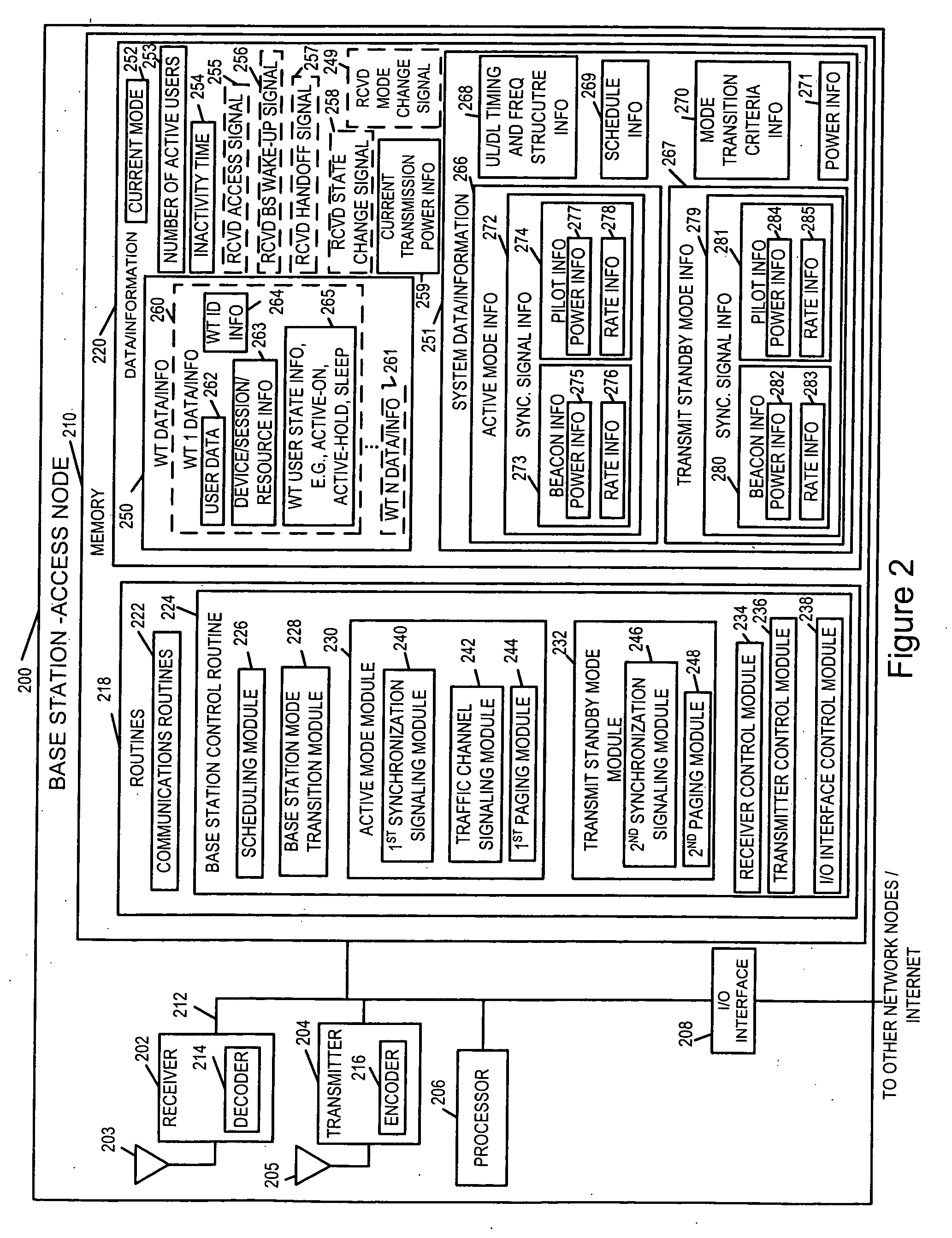
[0008] By supporting multiple modes of operation, base station transmissions of control signals can be reduced when the higher level of signaling is not required, e.g., when there are no active wireless terminals in the cell. By reducing base station transmissions in terms of frequency and / or power level, interference with communications in neighboring cells can be reduced. This allows for improved throughput in a multi-base station system where transmissions by adjoining base stations can interfere with one another. Depending on the particular mode of operation, the base station may support downlink signaling, e.g., broadcast transmission of data but not uplink transmissions of data which may require a higher level of control signaling. Modes which support both downlink and uplink communication of user data, e.g., text data, image data, audio data and / or user application data, between wireless terminals and a base station normally correspond to one or more higher, e.g., full-on, modes of base station operation.
[0009] During different modes of base station operation, different levels and / or rates of signaling and / or transmission output power are supported depending on the mode of operation. For example, in some embodiments, pilot signals and / or various control signals which are normally transmitted at a first periodic rate in a fully on state are transmitted at a reduced rate during a sleep mode of base station operation as compared to a full-on mode of base station operation. In some embodiments the number of pilot signals transmitted during a sleep mode is reduced during individual symbol transmission time periods during the sleep mode of operation as compared to the full-on mode of operation. In some embodiments, the number of individual symbol transmission time periods during which pilot signals are transmitted during the sleep mode of operation is reduced from the number of individual symbol transmission time periods during which pilot signals are transmitted in the full-on mode of operation, with respect to the same number of OFDM symbol transmission time periods, e.g., the same number of successive OFDM symbol transmission time periods representing a grouping in a repetitive downlink timing structure. In some embodiments, during a partial on or sleep mode of operation the power level at which particular signals are transmitted is reduced as compared to the power level used during the full-on mode of operation.
[0012] The methods and apparatus of the present invention support base stations with different modes of activity. While transmission power conservation is one benefit of supporting multiple base station modes of operation, the reduced level of signal interference achieved by supporting reduced activity modes of base station operation can increase overall system throughput by decreasing interference in neighboring cells when operating in a sleep state or other reduced activity mode of base station operation.

Problems solved by technology

Under such a situation, during such a time interval the base station power is wasted by transmitting the full set of synchronization signals at the normal power levels.
In addition, neighboring cells, which may have high population densities and typically have many active users, will be adversely affected by the interference generated from the unnecessary synchronization broadcast signaling.

Method used


Image

  • Methods and apparatus for use in a wireless communications system that uses a multi-mode base station
  • Methods and apparatus for use in a wireless communications system that uses a multi-mode base station
  • Methods and apparatus for use in a wireless communications system that uses a multi-mode base station

Examples


Embodiment Construction

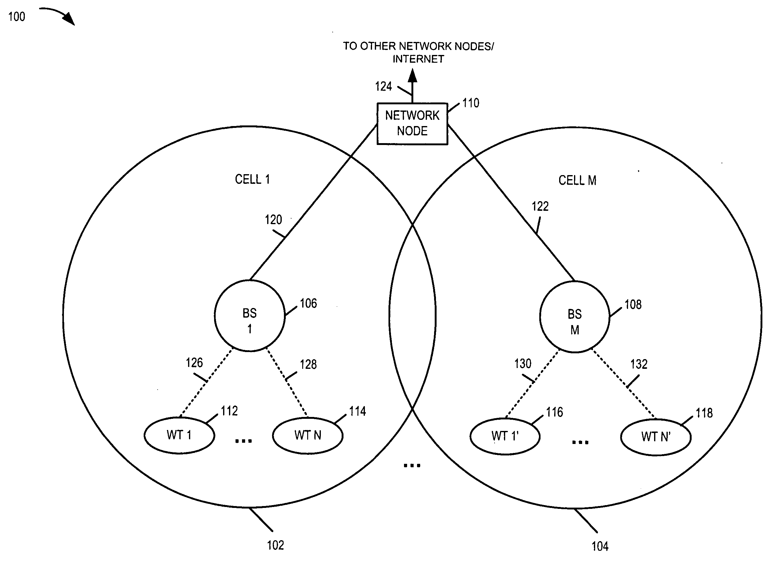
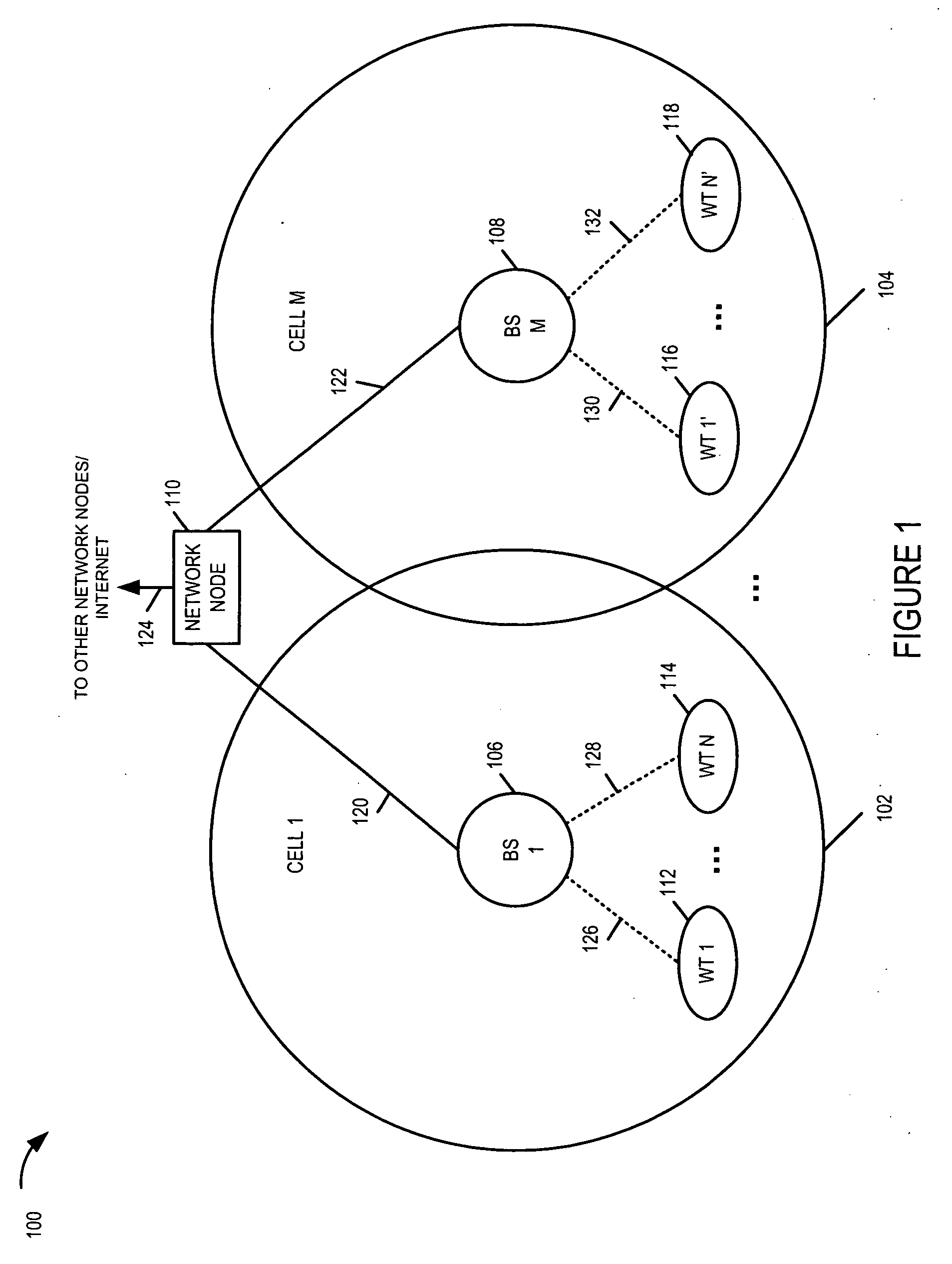
[0033]FIG. 1 is a drawing of an exemplary communications system 100 implemented in accordance with the present invention and using methods of the present invention. Exemplary communications system 100 may be, e.g., an orthogonal frequency division multiplexing (OFDM) multiple access wireless communications system. Exemplary system 100 includes a plurality of base stations (BS 1106, BS M 108), each BS (106, 108) having a corresponding cellular coverage area (cell 1102, cell M 104). The BSs (106, 108) are implemented in accordance with the present invention, and support (i) an active mode of operation and (ii) a transmit standby mode of operation. The BSs are coupled together via a backhaul network. System 100 also includes network node 110, e.g., a router. Network node 110 is coupled to (BS 1106, BS M 108) via network links (120, 122), respectively. Network link 124 couples network node 110 to other network nodes, e.g., other BSs, routers, Authentication-Authorization-Accounting (AAA...


PUM


Abstract

A multi-mode base station includes a transmit standby mode and an active mode. Transmit standby mode of base station operation is a low power / low interference level of operation as compared to active mode. In transmit standby mode at least some of the synchronization signaling such as pilot tone signaling is reduced in power level and / or rate with respect to the active mode. In transmit standby mode, the base station has no active state registered wireless terminals being serviced but may have some sleep state registered wireless terminals being serviced. Mode transitions from active to transmit standby may be in response to: a detected period of inactivity, scheduling information, base station mode change signals, and / or detected wireless terminal state transition. Mode transitions from transmit standby to active may be in response to: scheduling information, access signals, wake-up signals, hand-off signals, wireless terminal state change signals, and / or base station mode change signals.

Description

FIELD OF THE INVENTION [0001] The present invention relates to methods and apparatus for implementing wireless communications systems where the apparatus may include, for example, base stations which support multiple modes of operation and / or wireless terminals for interacting with base stations which support multiple modes of operation. BACKGROUND OF THE INVENTION [0002] Typically, in a wireless communications system, the base stations are powered on and continuously operated in an active mode of operation. In this active mode of operation, the base station is operated in accordance with a downlink timing and frequency structure, e.g., a repetitive timing and frequency structure. Synchronization signals, such as beacon signals and pilot signals, are transmitted on a scheduled basis at associated predetermined power levels. The power levels and rate of transmission of these synchronization signals do not typically vary regardless of the number and / or state of users being currently s...

Claims


Application Information

Patent Timeline
Patent Type & Authority Applications(United States)
IPC IPC(8): H04B7/00H04B15/00
CPCH04B7/2678H04L5/0007H04L5/0048Y02B60/50H04W56/00H04W72/1278H04W52/0206H04L5/0053H04W72/20Y02D30/70H04B7/155H04B7/15H04B15/00
Inventor LAROIA, RAJIVANIGSTEIN, PABLODAS, ARNABRANGAN, SUNDEEP
Owner QUALCOMM INC
Learn More