

An automatic agricultural organic manure spreader
A technology of organic manure and spreader, which is applied in the direction of manure spreading device, etc., which can solve the problems of reducing workload and uneven organic manure
Patent Information
- Authority / Receiving Office
- CN · China
- Patent Type
- Patents(China)
- Current Assignee / Owner
- Publication Date
- 2019-01-15
Smart Images
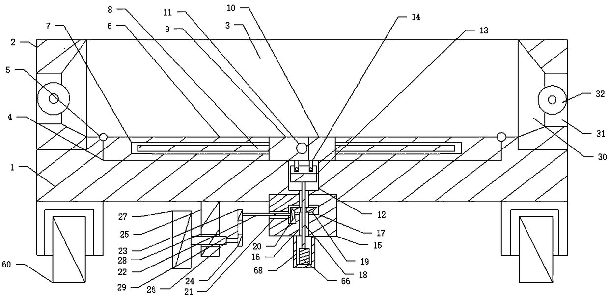
Figure 1 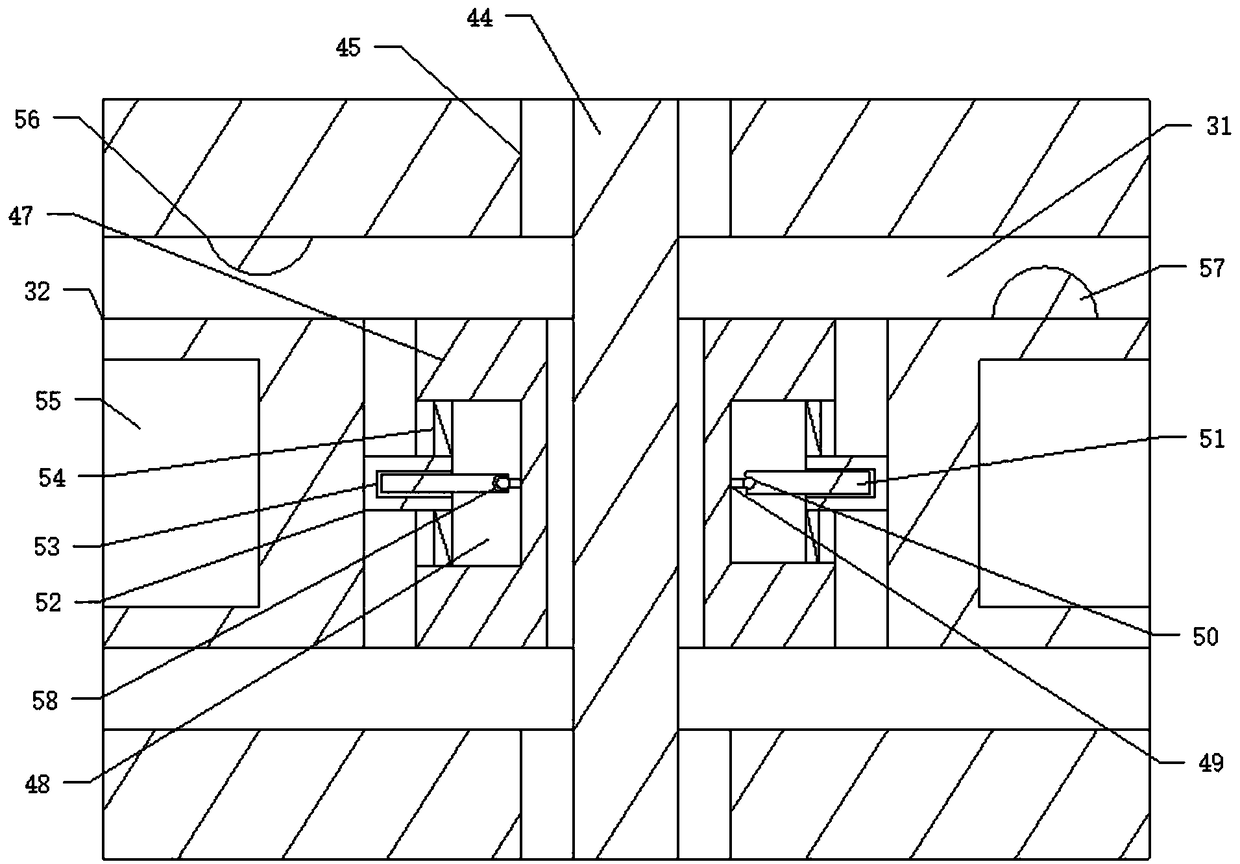
Figure 2 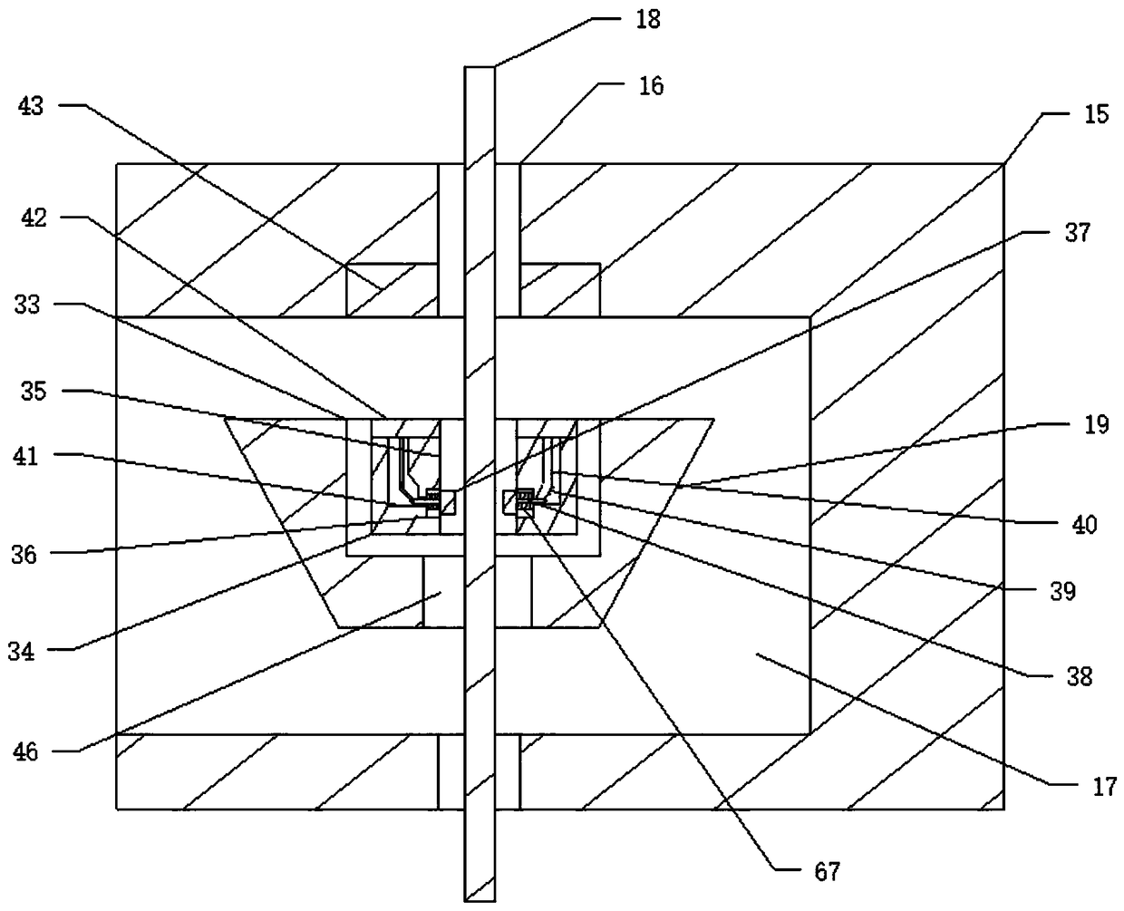
Figure 3
Abstract
Description
technical field
[0001] The invention relates to an agricultural fertilizer spreader, in particular to an automatic agricultural organic manure spreader, in particular to an agricultural organic manure spreader capable of uniformly spreading land and increasing the spreading area. Background technique
[0002] With the continuous development of science and technology, it has further promoted the continuous innovation of agricultural machinery. Among them, spreading fertilizer is one of the indispensable links in the current agricultural planting, so that the production of food can be further increased through fertilization. The harm to the human body is very great, so more and more organic manure is used in the agricultural production process. Most of the current organic manure fertilization processes are artificially fertilized, because the manure is easy to lead to sticky manure during the fermentation process. Because of the problem of clumps, it can only be fertilized man...
Examples
Embodiment Construction
[0031] Such as Figure 1 to Figure 9 As shown, an automatic agricultural organic manure spreader includes a carriage floor 1, a second roller 60 is respectively arranged on both sides of the carriage floor 1, and a carriage side plate 2 is respectively connected to both sides of the carriage floor 1. The compartment side plate 2 and the compartment bottom plate 1 form a compartment trough 3, and a row of discharge openings 31 corresponding to the compartment trough 3 are respectively arranged on the compartment side plates 2 on both sides. A main shaft 44 that rotates in the discharge port 31 is respectively arranged in the side panel 2 of the carriage, and a discharge runner 32 that rotates in the discharge port 31 is respectively arranged on the main shaft 44 . The material runner 32 swings in the mouth of the discharge 31, and a compartment side plate 2 is respectively connected to both sides of the compartment floor 1, and an inner groove is formed between the compartment ...