A light source arrangement method for an indoor visible light communication system

A technology for visible light communication and light source arrangement, which is applied in the direction of light guides, light sources, electric light sources, etc. Effect of layout cost, reliable transmission performance

Active Publication Date: 2019-03-19
ZHONGTIAN BROADBAND TECH +1
View PDF4 Cites 0 Cited by
  • Summary
  • Abstract
  • Description
  • Claims
  • Application Information

AI Technical Summary

Problems solved by technology

[0008] (4) The patent uses four LED lamp arrays for lighting, each array contains hundreds of sub-light sources and other supporting electronic components, the probability of failure is high, and the cost of installation, maintenance and replacement is high and difficult

Method used


Image

  • A light source arrangement method for an indoor visible light communication system
  • A light source arrangement method for an indoor visible light communication system
  • A light source arrangement method for an indoor visible light communication system

Examples


Embodiment Construction

[0046] The following will clearly and completely describe the technical solutions in the embodiments of the present invention. Obviously, the described embodiments are only some of the embodiments of the present invention, rather than all the embodiments. Based on the embodiments of the present invention, all other embodiments obtained by persons of ordinary skill in the art without making creative efforts belong to the protection scope of the present invention.

[0047] Please refer to the attached figure 1 , the embodiment of the present invention:

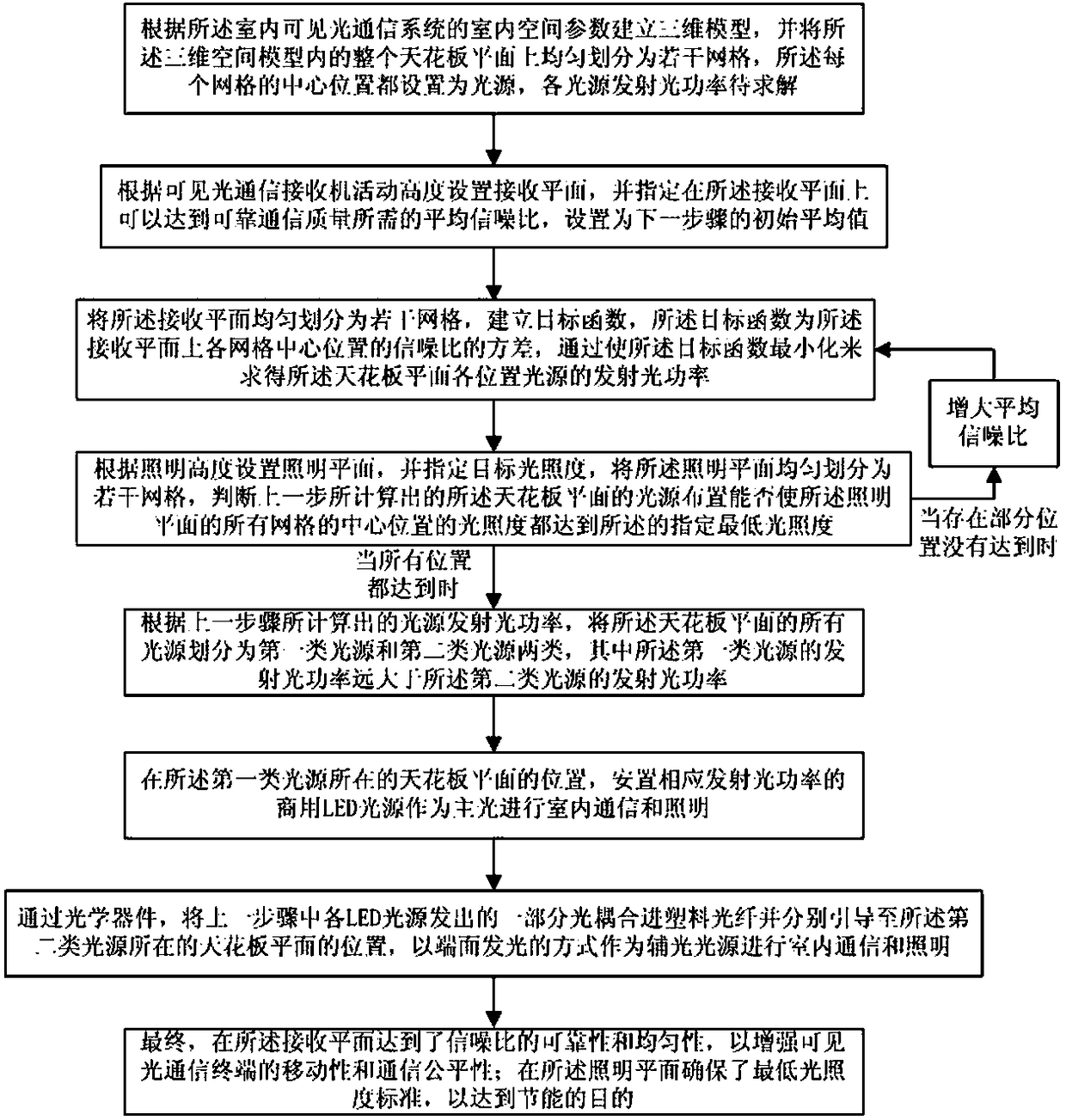
[0048] A method for arranging a light source in an indoor visible light communication system, which is used to determine the transmitted light power parameters to be calculated and the type of the light source at each position of the entire ceiling plane, and the steps are as follows:

[0049] (1) Establish a three-dimensional model according to the indoor space parameters of the indoor visible light communication system, and e...


PUM


Abstract

The invention relates to the visible light communication, the indoor visible light illumination, the indoor plastic optical fiber communication and the indoor plastic optical fiber illumination fields, and more particularly to a light source arranging method for an indoor visible light communication system. The method comprises: establishing a three-dimensional model based on the indoor spatial parameters; and calculating the light source power at each position of the entire ceiling plane by minimizing the variance of the received plane signal-to-noise ratio to ensure the indoor reliable and uniform communication quality and ensure that the illumination plane satisfies the minimum illumination intensity standard. According to the calculation result, the light source is divided into two types and the commercial LED light source with the corresponding emission power is arranged as the main light in the first type light source position, and a part of the light emitted from the LED light source is optically coupled into the plastic optical fiber through an optical device and is guided to the second type light source position as a secondary light source, therefore achieving indoor visible light communication and illumination combined by the LED and plastic optical fiber. The method can be performed simply, and at a low cost, the reliability and the uniformity of the communication quality are ensured, delivering the goal of conserving energy.

Description

technical field [0001] The present invention relates to the fields of indoor visible light communication, indoor visible light lighting, indoor plastic optical fiber communication and indoor plastic optical fiber lighting, and in particular relates to a light source arrangement method for an indoor visible light communication system. Background technique [0002] Energy-saving LED technology has become the first choice for indoor lighting facilities, and LED-based visible light communication, as an additional function on indoor lighting facilities, has the advantages of energy saving and environmental protection, not occupying scarce wireless spectrum resources, and good information confidentiality. , has become a research hotspot in the field of communication in recent years. On the other hand, plastic optical fiber is cheap, lightweight, has a large core diameter, good flexibility, and has many advantages such as anti-electromagnetic interference and high bandwidth. It has...

Claims


Application Information

Patent Timeline
Patent Type & Authority Patents(China)
IPC IPC(8): H04B10/116F21S8/00F21V8/00F21V19/00F21Y115/10
CPCF21S8/00F21V19/001F21V2200/17H04B10/116
Inventor 吴媛媛陈健由骁迪符小东何品翰李莉华王寅
Owner ZHONGTIAN BROADBAND TECH
Why Eureka
Try Eureka