Turbine engine oil reservoir with deaerator

A turbocharger and engine technology, applied in the directions of machines/engines, engine components, engine functions, etc., can solve problems such as unsatisfactory, consumption, multi-fuel, etc., to achieve simple solutions, increase reliability, and run energy. low effect

Active Publication Date: 2017-07-21
SAFRAN AERO BOOSTERS SA
View PDF6 Cites 4 Cited by
  • Summary
  • Abstract
  • Description
  • Claims
  • Application Information

AI Technical Summary

Problems solved by technology

This is not satisfactory because the turbojet engine will be heavier and the corresponding aircraft will consume more fuel when it is lifted into the air

Method used


Image

  • Turbine engine oil reservoir with deaerator
  • Turbine engine oil reservoir with deaerator
  • Turbine engine oil reservoir with deaerator

Examples


Embodiment Construction

[0053] In the description, the terms "inner or inner and outer or outer" refer to a position relative to the axis of rotation of the axial turbocharged engine. The axial direction corresponds to the direction along the axis of rotation of the rotor of the air vent. The radial direction is perpendicular to the axis of rotation.

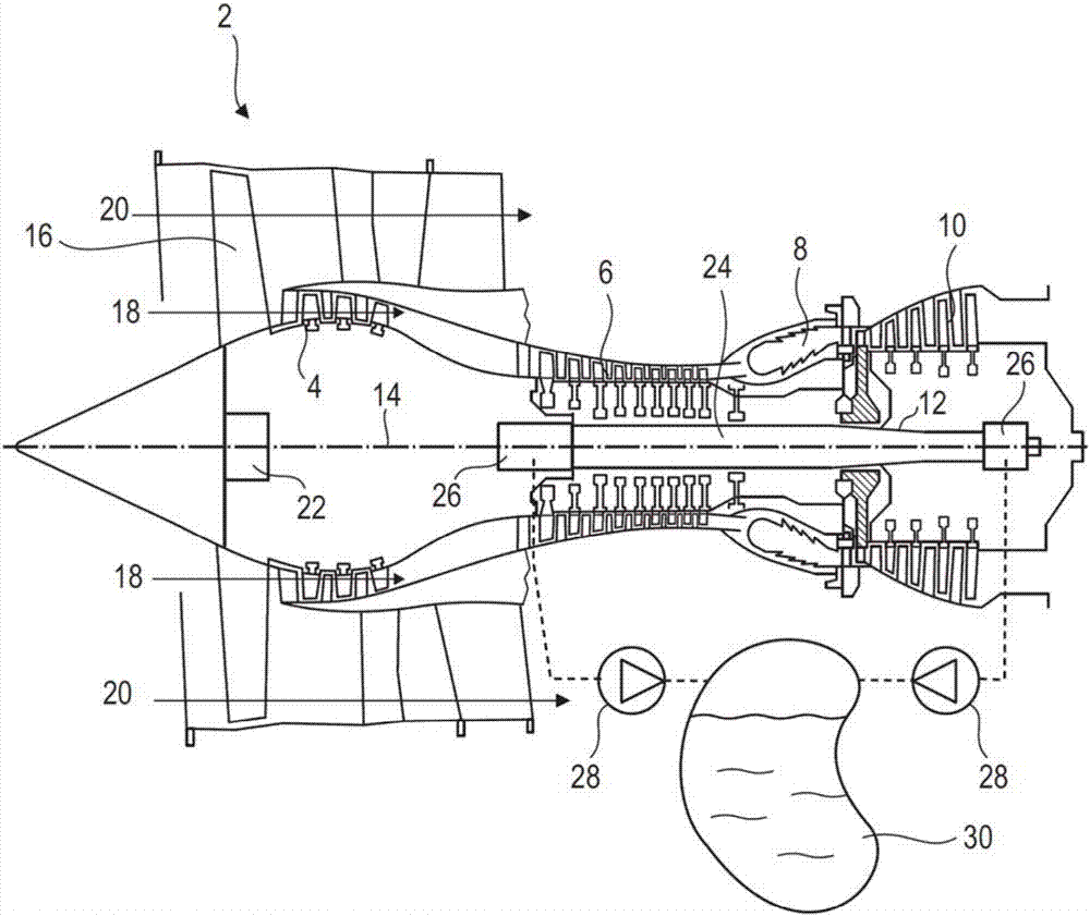
[0054] figure 1 An axial turbocharged engine is shown in a simplified manner. In this particular case, it is a bypass turbojet engine. The turbojet engine 2 comprises a first compression stage called a low-pressure compressor 4 , a second compression stage called a high-pressure compressor 6 , a combustion chamber 8 and one or more turbine stages 10 . During operation, the mechanical power of the turbine 10 transmitted via the central shaft to the rotor 12 sets the two compressors 4 and 6 into motion. The two compressors include rows of rotor blades associated with rows of stator blades. The rotation of the rotor about its axis of rotation 14 thus...


PUM


Abstract

A turbine engine reservoir has an oil deaerating device. The oil deaerating device includes a deaeration chamber for an air-oil mixture; an inlet of the air-oil mixture with a tangential inlet channel to form a vortex in the air-oil mixture contained in the chamber; and a vent for the discharge of air as a result of the deaeration of the air-oil mixture. The vent includes a rotor driven in rotation by the circulation of the air-oil mixture in the region of the inlet. The rotor filters the degassed air loaded with oil droplets in suspension. By centrifugal force, the rotor returns the collected oil onto the internal surface of the conduit of the vent. The collected oil drops back down into the chamber as a result of gravity.

Description

technical field [0001] The invention relates to the field of oil degassing devices. More specifically, the present invention relates to an engine oil reservoir provided with a degasser and a vent hole for discharging gas removed from the oil. The present invention further proposes a turbocharged engine (turboengine), which specifically proposes an aircraft turbojet engine or an aircraft turboprop engine. Background technique [0002] A multi-flow turbojet comprises a number of independent rotors articulated relative to the stator chamber. Its pivot connection is implemented by lubricated bearings in a chamber filled with oil mist. The oil is sprayed onto the rolling bearings and then collected for return to the oil reservoir of the turbojet engine. During operation, a gas-oil mixture is formed which reduces the performance of the oil. [0003] In order to reduce the effect of air bubbles in this mixture, the reservoir is connected to a degassing device which allows air t...

Claims


Application Information

Patent Timeline
Patent Type & Authority Applications(China)
IPC IPC(8): F02C7/06B01D19/00F16N39/00
CPCB01D19/0057F02C7/06F16N39/002B01D19/0052B01D19/02B01D45/16F01D25/18F05D2260/608F01M2011/038F01M11/03B01D46/0056B04C5/04B04C9/00B04C2009/004F01D25/183F01D25/20F05D2260/609
Inventor N.雷马克斯A.科尔内特B.瑟维斯S.博格莱特
Owner SAFRAN AERO BOOSTERS SA
Why Eureka
Try Eureka