Direct current circuit breaker of mixed switching device

A technology of DC circuit breakers and switching devices, applied in the direction of electric switches, electronic switches, emergency protection devices for automatic disconnection, etc., can solve the problems of difficult regulation and high cost, reduce the impact of commutation, high reliability, and ensure fast sexual effect

Inactive Publication Date: 2017-07-21
INST OF ELECTRICAL ENG CHINESE ACAD OF SCI
View PDF5 Cites 5 Cited by
  • Summary
  • Abstract
  • Description
  • Claims
  • Application Information

AI Technical Summary

Problems solved by technology

[0006] The purpose of the present invention is to overcome the shortcomings of the prior art that the cost is high a

Method used


Image

  • Direct current circuit breaker of mixed switching device
  • Direct current circuit breaker of mixed switching device
  • Direct current circuit breaker of mixed switching device

Examples


Embodiment 1

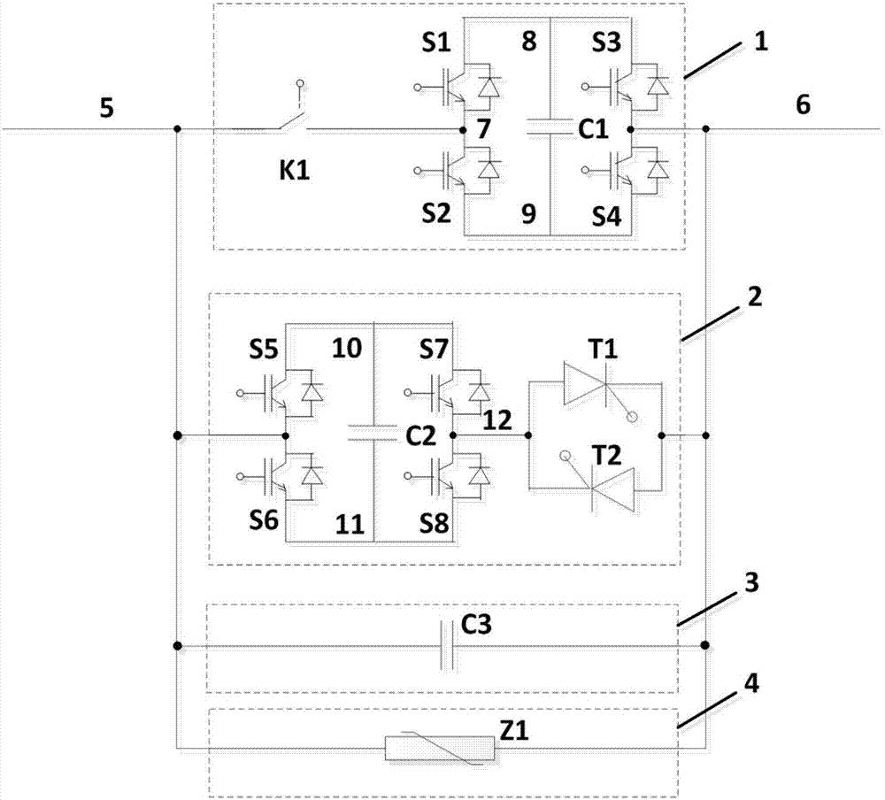
[0035] figure 1 Shown is Example 1 of the present invention. Such as figure 1 As shown, the DC circuit breaker of the present invention is composed of a first current path 1, a second current path 2, a third current path 3, and a fourth current path 4. The first current path 1 consists of a first mechanical switch K1, a first capacitor C1, a first fully-controlled switching device S1, a second fully-controlled switching device S2, a third fully-controlled switching device S3, and a fourth fully-controlled switch The device S4 is composed; the second current path 2 is composed of the second capacitor C2, the fifth full-control switching device S5, the sixth full-control switching device S6, the seventh full-control switching device S7, and the eighth full-control switching device S8 , The first half-controlled switching device T1 and the second half-controlled switching device T2 are composed; the third current path 3 is composed of the third capacitor C3; the fourth current pat...

Embodiment 2

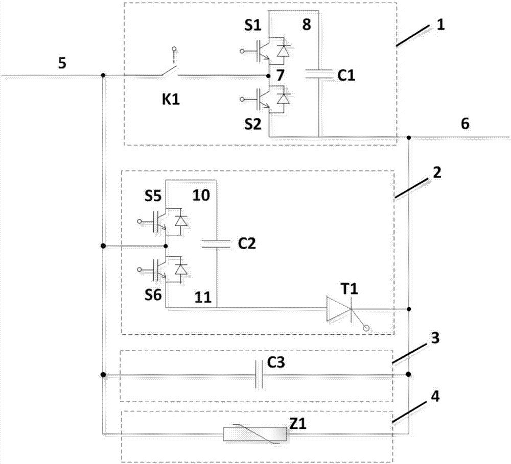
[0040] figure 2 Shown is Example 2 of the present invention. Such as figure 2 As shown, the DC circuit breaker of the present invention is composed of a first current path 1, a second current path 2, a third current path 3, and a fourth current path 4. The first current path 1 is composed of the first mechanical switch K1, the first capacitor C1, the first fully-controlled switching device S1, and the second fully-controlled switching device S2; the second current path 2 is composed of the second capacitor C2 and the fifth The control switch device S5, the sixth full control switch device S6, and the first half control switch device T1 are composed; the third current path 3 is composed of the third capacitor C3; the fourth current path 4 is composed of the first arrester Z1.

[0041] The first lead terminal of the first mechanical switch K1, the second lead terminal of the fifth fully controlled switching device S5, the first lead terminal of the sixth fully controlled switchin...

Embodiment 3

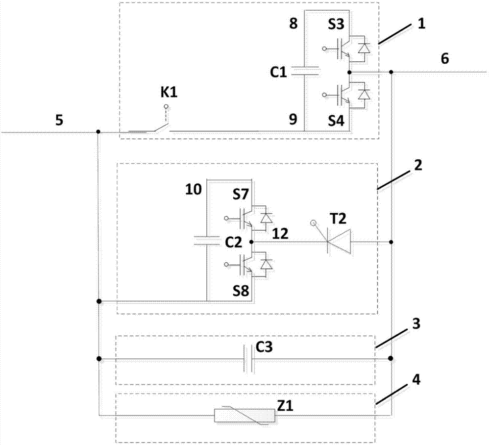
[0044] image 3 Shown is Example 3 of the present invention. Such as image 3 As shown, the DC circuit breaker of the present invention is composed of a first current path 1, a second current path 2, a third current path 3, and a fourth current path 4. The first current path 1 is composed of the first mechanical switch K1, the first capacitor C1, the third fully-controlled switching device S3, and the fourth fully-controlled switching device S4; the second current path 2 is composed of the second capacitor C2 and the seventh The control switch device S7, the eighth full control switch device S8, and the second half control switch device T2 are composed; the third current path 3 is composed of the third capacitor C3; the fourth current path 4 is composed of the first lightning arrester Z1.

[0045] The first lead-out terminal of the first mechanical switch K1, the second lead-out terminal of the second capacitor C2, the second lead-out terminal of the eighth fully-controlled switc...


PUM


Abstract

The invention provides a direct current circuit breaker of a mixed switching device. The direct current circuit breaker consists of a first mechanical switch (K1), a first capacitor (C1), a second capacitor (C2), a third capacitor (C3), a first full-controlled switch device (S1), a second full-controlled switch device (S2), a third full-controlled switch device (S3), a fourth full-controlled switch device (S4), a fifth full-controlled switch device (S5), a sixth full-controlled switch device (S6), a seventh full-controlled switch device (S7), an eighth full-controlled switch device (S8), a first half-controlled switch device (T1), a second half-controlled switch device (T2) and a first light arrester (Z1). By controlling turning on and turning off of the full-controlled switch devices and the half-controlled switch devices, rapid turning on and turning off of fault current of a direct current power grid are achieved.

Description

Technical field [0001] The invention relates to a circuit breaker, in particular to a DC circuit breaker. Background technique [0002] The damping of the DC system is low. Compared with the AC system, the control and protection of the DC system is more difficult. And for the flexible DC transmission system based on fully controlled semiconductor devices, the device has a weak overcurrent withstand capability, and the fault current may exceed the maximum withstand value of the device within a few milliseconds, causing damage to key devices and even the entire converter station. Therefore, it is necessary to quickly limit and cut off the fault current in order to maintain the safe and stable operation of the DC grid and protect the key equipment in the grid. High-voltage DC circuit breakers become effective or even the only devices that quickly limit and cut off fault currents. Since the DC current has no natural zero crossing point, the DC arc is not easy to extinguish. None o...

Claims


Application Information

Patent Timeline
IPC IPC(8): H01H9/54H02H3/087H03K17/51
CPCH01H9/548H02H3/087H03K17/51H03K2017/515
Inventor 尹靖元霍群海吴理心王欣未韦统振
Owner INST OF ELECTRICAL ENG CHINESE ACAD OF SCI
Why Eureka
Try Eureka