A DC circuit breaker

A technology of DC circuit breakers and DC transmission lines, which is applied in circuits, circuit devices, high-voltage/high-current switches, etc., can solve the problems that the breaking time is difficult to meet the DC transmission system, and the current cannot be turned off, so as to achieve rapid topological breaking, The effect of protecting safety and reducing loss

Active Publication Date: 2016-01-20
INST OF ELECTRICAL ENG CHINESE ACAD OF SCI
View PDF6 Cites 0 Cited by
  • Summary
  • Abstract
  • Description
  • Claims
  • Application Information

AI Technical Summary

Problems solved by technology

Different from the AC system, the current of the DC system does not have a natural zero-crossing point, so the natural zero-crossing point of the current cannot be used in the DC system like the AC system. Therefore, the breaking of the DC current has always been a problem worth studying. Subject
The hybrid circuit breaker manufactured by using this principle has special requirements for mechanical switches, and it is difficult to meet the requirements of the DC transmission system in terms of breaking time.

Method used


Image

  • A DC circuit breaker
  • A DC circuit breaker
  • A DC circuit breaker

Examples


Embodiment 1

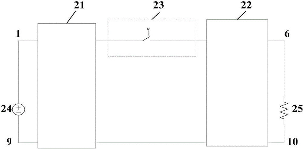
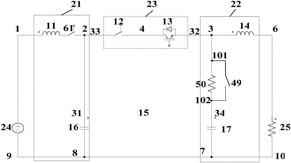
[0047] figure 2 Shown is Example 1 of the present invention. Such as figure 2 As shown, the DC power supply 24 is a converter station, and the resistor 25 is a short-circuit resistor. The basic structure of the DC breaking topology of the present invention includes: an initial current path 23 , a first combined circuit 21 , a second combined circuit 22 and a voltage limiter 15 . The initial current path includes a power electronics module 13 and a mechanical switch module 12; the first combined loop includes an inductor 11 and a capacitor 16, and the second combined loop includes an inductor 14, a capacitor 17, and a capacitor The charging circuit has a built-in switch 5, 0 and a capacitor charging circuit resistor 49.

[0048] The initial current path includes a power electronics module 13 and a mechanical switch module 12; the first combined loop includes an inductor 11, a capacitor 16 and a built-in mechanical switch 61, and the second combined loop includes an inducto...

Embodiment 2

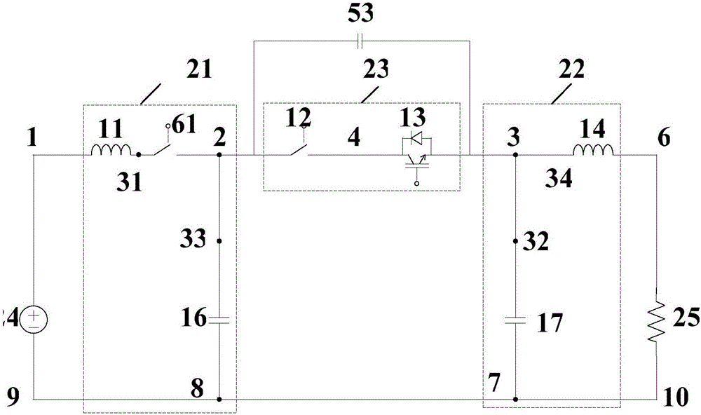
[0052] image 3 Shown is Example 2 of the present invention. image 3 The two ends of the capacitor 53 are connected to the two ends of the initial current loop 23 respectively.

Embodiment 3

[0054] Figure 4 Shown is embodiment 3 of the present invention, between the first combined loop second lead-out terminal 2 and one end 33 of the first combined loop capacitor, add a capacitor pre-charging circuit 41, and the pre-charging circuit 41 is composed of a pre-charging resistor 44, a pre-charging switch 45 and a precharge bypass switch 46, one end of the precharge resistor 44 is connected to one end of the precharge switch 45, and the other end of the precharge resistor 44 is used as the first lead-out terminal of the precharge circuit 41 to connect with the precharge bypass switch 46 One end is connected, and the other end of the pre-charging switch 45 is connected to the other end of the pre-charging bypass switch 46 as the second lead-out terminal of the pre-charging circuit 41 . When the system is just started, the pre-charge switch 45 is closed, and the pre-charge bypass switch 46 is disconnected to pre-charge the short-circuit oscillating current path capacitor...


PUM


Abstract

A direct-current circuit breaker consists of an initial current passage (23), a first combination loop (21), and a second combination loop (22). A first leading-out terminal of the initial current passage (23) is connected to a second leading-out terminal of the first combination loop (21). A second leading-out terminal of the initial current passage (23) is connected to a first leading-out terminal of the second combination loop (22). The first leading-out terminal of the first combination loop (21) serves as a first leading-out terminal of the direct-current circuit breaker and is connected to a direct-current power transmission line. The second leading-out terminal of the second combination loop (22) serves as a second leading-out terminal of the direct-current circuit breaker and is connected to the other end of the direct-current power transmission line. When a high-voltage direct-current power transmission circuit is failed, the failed power transmission circuit can be quickly switched off.

Description

technical field [0001] The invention relates to a circuit breaker, in particular to a direct current circuit breaking topology and a control method thereof. Background technique [0002] Fast DC circuit breaker is one of the key equipment to ensure the stable, safe and reliable operation of DC power transmission and distribution system and DC grid system. Different from the AC system, the current of the DC system does not have a natural zero-crossing point, so the natural zero-crossing point of the current cannot be used in the DC system like the AC system. Therefore, the breaking of the DC current has always been a problem worth studying. topic. [0003] At present, there are usually two ways to break the DC current. The first is a pure power electronic circuit breaker, such as the patent CN102870181A applied by ABB, which can turn off the power electronic device by using high power and directly break the DC current. Although the solid-state circuit breaker manufactured b...

Claims


Application Information

Patent Timeline
Patent Type & Authority Patents(China)
IPC IPC(8): H01H71/08H02H3/087
CPCH01H9/548H01H33/16H01H33/596H02H3/025H02H3/087
Inventor 肖立业韦统振朱晋王珏邱清泉张志丰林良真齐智平李耀华严萍
Owner INST OF ELECTRICAL ENG CHINESE ACAD OF SCI
Why Eureka
Try Eureka