A DC circuit breaker topology

A DC circuit breaker and current path technology, applied in circuits, electrical components, electrical switches, etc., can solve the problems of high cost of DC circuit breakers, influence of breaking speed, and inability to turn off current, and achieves fast topology breaking and opening. The effect of fast breaking speed and low manufacturing difficulty

Active Publication Date: 2016-03-02
INST OF ELECTRICAL ENG CHINESE ACAD OF SCI
View PDF6 Cites 1 Cited by
  • Summary
  • Abstract
  • Description
  • Claims
  • Application Information

AI Technical Summary

Problems solved by technology

Different from the AC system, the current of the DC system does not have a natural zero-crossing point, so the natural zero-crossing point of the current cannot be used in the DC system like the AC system. Therefore, the breaking of the DC current has always been a problem worth studying. Subject
However, when the capacitance value is large, the breaking speed will be affected
[0006] ABB’s patent WO2011141054A1 proposes a hybrid circuit breaker, in which a mechanical switch and a power electronic full-control device are connected in series on the main path, and the other bypass is composed of a surge arrester and a crimped IGBT connected in parallel. When a fault current is detected, the voltage on the bypass The IGBTs are all turned on, and then the power electronic full-control devices on the main path are disconnected, and the mechanical switch is also turned off. After the mechanical switch is completely turned off, the crimping IGBT is turned off, and the arrester is connected to the circuit to suppress the short-circuit current. The breaking speed of the circuit breaker is fast, but the sum of the withstand voltage of the crimped IGBTs of the entire bypass must be greater than the initial voltage of the DC transmission line, which requires a large number of crimped IGBTs to be connected in series, resulting in a higher cost for the entire DC circuit breaker
[0007] Moreover, the main circuits of the above two patents must use full-control switching devices in series with mechanical switches, resulting in large conduction losses in normal conditions.

Method used


Image

  • A DC circuit breaker topology
  • A DC circuit breaker topology
  • A DC circuit breaker topology

Examples


Embodiment 1

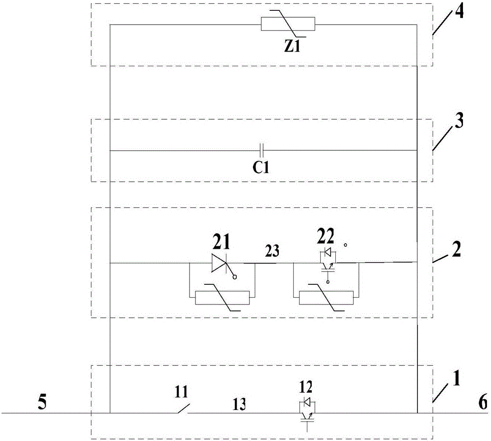
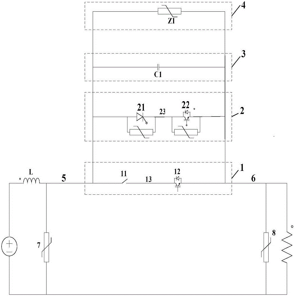
[0050] figure 2 Shown is Example 1 of the present invention. like figure 2 As shown, the voltage source 15 is a converter station, and the resistor 16 is a simulated short-circuit resistor. The DC circuit breaker of the present invention is composed of a first current path 1, a second current path 2, a third current path 3 and a fourth current path 4; Lead-out terminals, the first lead-out terminal of the second current path and the first lead-out terminal of the first current path are connected together, as the first lead-out terminal 5 of the DC circuit breaker is connected with one end of the DC transmission line; the fourth current path 4 The second lead-out terminal, the second lead-out terminal of the third current path 3, the second lead-out terminal of the second current path 2 and the second lead-out terminal of the first current path are connected together, as the second lead-out terminal 6 of the DC circuit breaker and Connect the other end of the DC power line...

Embodiment 2

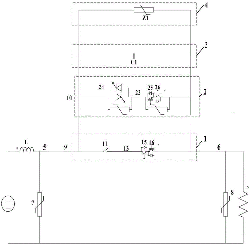
[0058] image 3 Shown is Example 2 of the present invention. like image 3 As shown, the half-controlled device module 21 of the second current path 2 is composed of at least one anti-parallel half-controlled device unit 24 connected in series. The fully-controlled device module 22 of the second current path 2 is composed of the first group of fully-controlled devices 25 of the second current path and the second group of fully-controlled devices 26 of the second current path in reverse series. Both the controlled device 25 and the second group of fully controlled devices 26 are composed of at least one fully controlled device connected in series in the same direction. The fully-controlled device module of the first current path 1 is composed of a first group of fully-controlled devices 15 in the first current path and a second group of fully-controlled devices 16 in the first current path;

Embodiment 3

[0060] Figure 4 Shown is Example 3 of the present invention. like Figure 4 As shown, this embodiment omits the first current path 1, and the entire DC circuit breaker is only composed of the second current path 2, the third current path 3 and the fourth current path 4, and the shut-off speed of the fault current is faster, but It also increases the conduction loss during normal operation of the system.


PUM


Abstract

The invention relates to a direct-current breaker topology comprising a first current path (1), a second current path (2), a third current path (3) and a fourth current path(4). A first leading-out terminal of the fourth current path (4), a first leading-out terminal of the third current path (3), a first leading-out terminal of the second current path (2), and a first leading-out terminal of the first current path (1) are connected together to form a first leading-out terminal (5) of the direct-current breaker; and the first leading-out terminal (5) is connected with one end of a direct-current power transmission line. A second leading-out terminal of the fourth current path (4), a second leading-out terminal of the third current path (3), a second leading-out terminal of the second current path (2), and a second leading-out terminal of the first current path (1) are connected together to form a second leading-out terminal (6) of the direct-current breaker; and the second leading-out terminal (6) is connected with the other end of the direct-current power transmission line. When the system works normally, the direct-current breaker has the low loss; and when a fault occurs at a high-voltage direct-current power transmission line, the fault power transmission line can be disconnected rapidly.

Description

technical field [0001] The invention relates to a circuit breaker, in particular to a DC circuit breaker. Background technique [0002] Fast DC circuit breaker is one of the key equipment to ensure the stable, safe and reliable operation of DC power transmission and distribution system and DC grid system. Different from the AC system, the current of the DC system does not have a natural zero-crossing point, so the natural zero-crossing point of the current cannot be used in the DC system like the AC system. Therefore, the breaking of the DC current has always been a problem worth studying. topic. [0003] At present, there are usually two ways to break the DC current. The first is a pure power electronic circuit breaker, such as the patent CN102870181A applied by ABB, which can turn off the power electronic device by using high power and directly break the DC current. Although the solid-state circuit breaker manufactured by this principle can meet the requirements of the m...

Claims


Application Information

Patent Timeline
Patent Type & Authority Patents(China)
IPC IPC(8): H01H9/54
Inventor 韦统振朱晋肖立业
Owner INST OF ELECTRICAL ENG CHINESE ACAD OF SCI
Why Eureka
Try Eureka