DC circuit breaker based on semi-controlled power electronic devices
A technology of power electronic devices and DC circuit breakers, which is applied in the field of DC circuit breaker topology, can solve the problems of high cost of DC circuit breakers, the influence of breaking speed, and the inability to turn off the current, so as to achieve low loss, rapid breaking, and protection safety Effect
- Summary
- Abstract
- Description
- Claims
- Application Information
AI Technical Summary
Problems solved by technology
Method used
Image
Examples
Embodiment 1
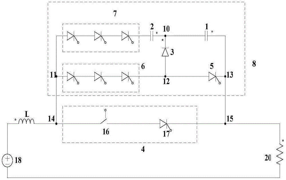
[0049] figure 2 Shown is Example 1 of the present invention. Such as figure 2 As shown, the DC power supply 18 is a simulated converter station, the resistor 20 is a short-circuit simulated resistor, and the inductance L is a DC reactor configured in each converter station in the DC grid, or it can also be a limit fault current rising rate configured in a DC circuit breaker. the reactor.
[0050] The positive pole of the DC power supply 18 is connected to one end of the inductor L, and the other end of the DC power supply 18 is connected to the ground or the neutral line. The other end of the inductor L is connected to the first lead-out terminal of the DC circuit breaker, the second lead-out terminal of the DC circuit breaker is connected to one end of the resistor 20, and the other end of the resistor 20 is connected to the ground or the neutral line.
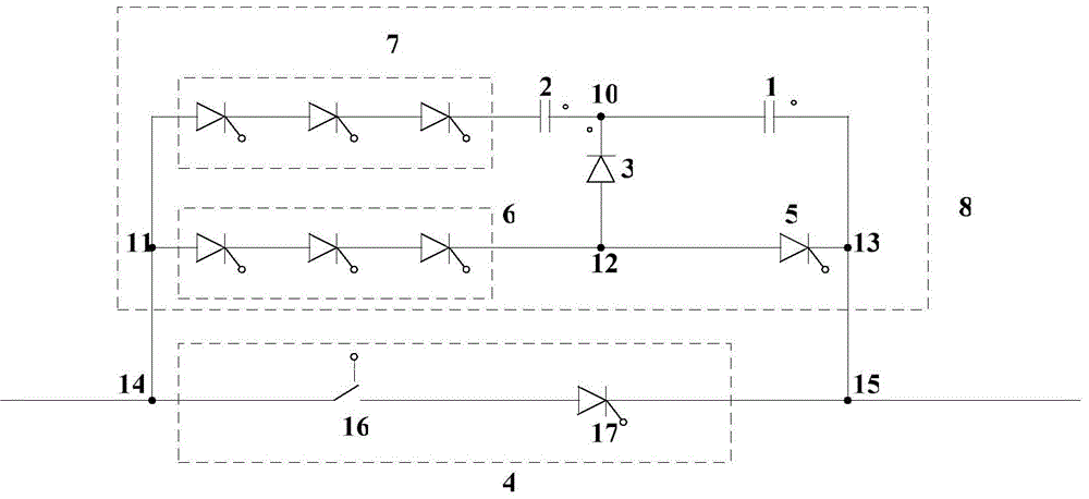
[0051] The DC circuit breaker is composed of an initial current path 4 and a fault current blocking path 8 . The firs...
Embodiment 2
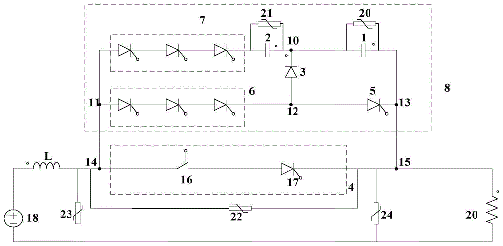
[0058] image 3 Shown is Example 2 of the present invention. image 3 The two ends of the initial current path 4 in the fault current blocking path 8 are connected in parallel with a voltage limiting device 20 at both ends of the first capacitor module 1, and the two ends of the second capacitor module 2 are connected in parallel with a voltage limiting device 21. A voltage limiter 22 is connected in parallel at both ends. It is also possible to selectively add voltage limiting devices at both ends of the place where protection is required.
Embodiment 3
[0060] Figure 4 Shown is Example 3 of the present invention. Such as Figure 4 As shown, the diode module 3 consists of Figure 4 wires in the . After the line short-circuit fault is detected, the first half-controlled device module 5 and the second half-controlled device module 6 receive a trigger signal, and the first capacitor module 1 discharges, causing the current of the fault current blocking path 8 to flow through the second The current of the half-controlled device module 5 and the diode module 3 and the first capacitor module 1 increases rapidly. Since the current on the inductor L cannot change abruptly, the current on the initial current path 4 decreases rapidly, and the fault current is quickly switched from the initial current path 4 to the fault current blocking path 8, and the fault current flows through the second half-controlled device module 5 , the diode module 3 and the first capacitor module 1; the current in the initial current path 4 quickly drops ...
PUM
 Abstract
Description
Claims
Application Information
 - R&D
- Intellectual Property
- Life Sciences
- Materials
- Tech Scout
- Unparalleled Data Quality
- Higher Quality Content
- 60% Fewer Hallucinations
Browse by: Latest US Patents, China's latest patents, Technical Efficacy Thesaurus, Application Domain, Technology Topic, Popular Technical Reports.
© 2025 PatSnap. All rights reserved.Legal|Privacy policy|Modern Slavery Act Transparency Statement|Sitemap|About US| Contact US: help@patsnap.com


