Heat pipe

A technology of heat pipes and headers, applied in heat transfer modification, heat exchange equipment, indirect heat exchangers, etc., can solve problems such as inability to stabilize flow, difficulty in entering and passing fluid, and affecting fluid heat exchange, etc., to reduce Noise and vibration, improve the effect of steady flow, enhance the effect of heat transfer

Active Publication Date: 2017-08-18
JIANGSU TONGSHENG HEAT EXCHANGER
View PDF4 Cites 5 Cited by
  • Summary
  • Abstract
  • Description
  • Claims
  • Application Information

AI Technical Summary

Problems solved by technology

However, it was found during the operation of this device that the space A formed between the three pipes is relatively small because the pipes are tightly combined, because the space A is formed by the convex arc of the three pipes, so most of the space A Narrowness will make it difficult for the fluid to enter and pass through, resulting in a short circuit of the fluid, which affects the heat transfer of the fluid and cannot play a good role in stabilizing the flow
Simultaneously because the many tubes of above-mentioned structure are combined together, manufacture difficulty
[0007] In view of the above problems, the present invention has been improved on the basis of the previous invention, and a new heat pipe is provided, thereby solving the problems of low heat transfer coefficient and uneven heat transfer in the case of heat pipe heat exchange

Method used


Image

  • Heat pipe
  • Heat pipe
  • Heat pipe

Examples


Embodiment Construction

[0045] The specific embodiments of the present invention will be described in detail below in conjunction with the accompanying drawings.

[0046] In this article, if there is no special explanation, when it comes to formulas, " / " means division, and "×" and "*" mean multiplication.

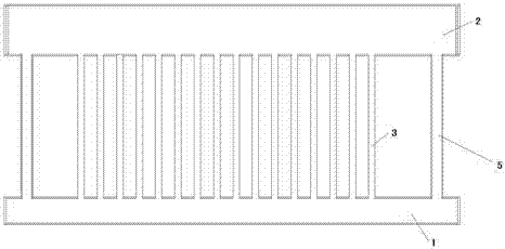
[0047] like figure 1 A heat pipe shown includes an evaporation header 1, a condensation header 2, a rising pipe 3 and a return pipe 5, the rising pipe 3 communicates with the evaporation header 1 and the condensation header 2, and the evaporation header 1 Located in the lower part, the condensation header 2 is located in the upper part, the fluid absorbs heat and evaporates in the evaporation header 1, enters the condensation header 2 through the riser 3, condenses after exchanging heat in the condensation header 2, and the condensed fluid Return to the evaporation header 1 through the return pipe 5.

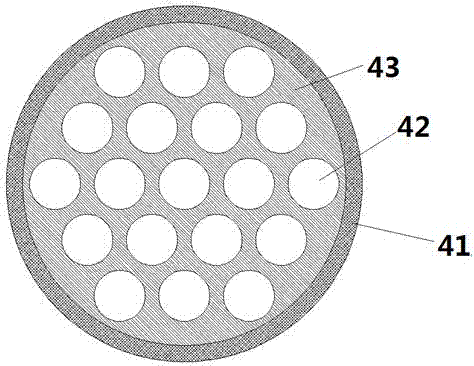
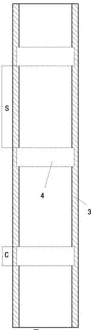
[0048] like Figure 4-5 As shown, a porous flow stabilizing device 4 is arranged in the ris...


PUM


Abstract

The invention provides a heat pipe which comprises an evaporation header, a condensation header, a rising pipe and a backflow pipe. The rising pipe is communicated with the evaporation header and the condensation header, the evaporation header is located at the lower portion, the condensation header is located at the upper portion, fluid absorbs heat and evaporates in the evaporation header, passes through the rising pipe to enter the condensation header and conducts heat exchange and condensation in the condensation header, and condensation fluid returns to the evaporation header through the backflow pipe; and a current stabilizer is arranged in the rising pipe and comprises a core body and a shell, the core is arranged in the shell, the shell is fixedly connected with the inner wall of the rising pipe, the core is an integrated structure piece extending in the length direction of the shell, and a plurality of through holes are formed in the structure piece. According to the heat pipe with the current stabilizer of the new structure, when vapor-liquid two-phase flow exists in the rising pipe, heat transfer strengthening is achieved; and meanwhile, vibration of the rising pipe is weakened, and the noise level is reduced.

Description

technical field [0001] The invention belongs to the field of heat pipes, in particular to a heat exchange heat pipe. Background technique [0002] Heat pipe technology is a heat transfer element called "heat pipe" invented by George Grover of Los Alamos National Laboratory in the United States in 1963. It makes full use of the principle of heat conduction and phase change medium. The rapid heat transfer properties of the heat pipe quickly transfer the heat of the heating object to the heat source, and its thermal conductivity exceeds that of any known metal. [0003] Heat pipe technology was widely used in aerospace, military and other industries before. Since it was introduced into the radiator manufacturing industry, people have changed the traditional radiator design ideas and got rid of the single heat dissipation mode that only relies on high air volume motors to obtain better heat dissipation. The use of heat pipe technology enables the radiator to obtain a satisfacto...

Claims


Application Information

Patent Timeline
Patent Type & Authority Applications(China)
IPC IPC(8): F28D15/02
CPCF28D15/02F28D15/0266F28F13/08F28F2265/28F28F2265/30
Inventor 郭春生刘勇齐超宋金圣邓伊涵高军宁淑荣张斌曲芳仪陈子昂年显勃李言伟
Owner JIANGSU TONGSHENG HEAT EXCHANGER
Why Eureka
Try Eureka