New-type helical antenna

A helical antenna and a new type of technology, applied in the field of antennas, can solve the problems of complex processing technology, large phase error, poor consistency, etc., and achieve the effects of small size, small phase center deviation, and speeding up production efficiency.

Pending Publication Date: 2017-08-29
西安巨向导航科技有限公司
View PDF11 Cites 5 Cited by
  • Summary
  • Abstract
  • Description
  • Claims
  • Application Information

AI Technical Summary

Problems solved by technology

[0003] The traditional helical antenna is made of copper wire or other metals, the processing technology is complicated, the bandwidth is narrow, the consistency is poor, the profile is high, and the phase error is large

Method used


Image

  • New-type helical antenna
  • New-type helical antenna
  • New-type helical antenna

Examples


Embodiment 1

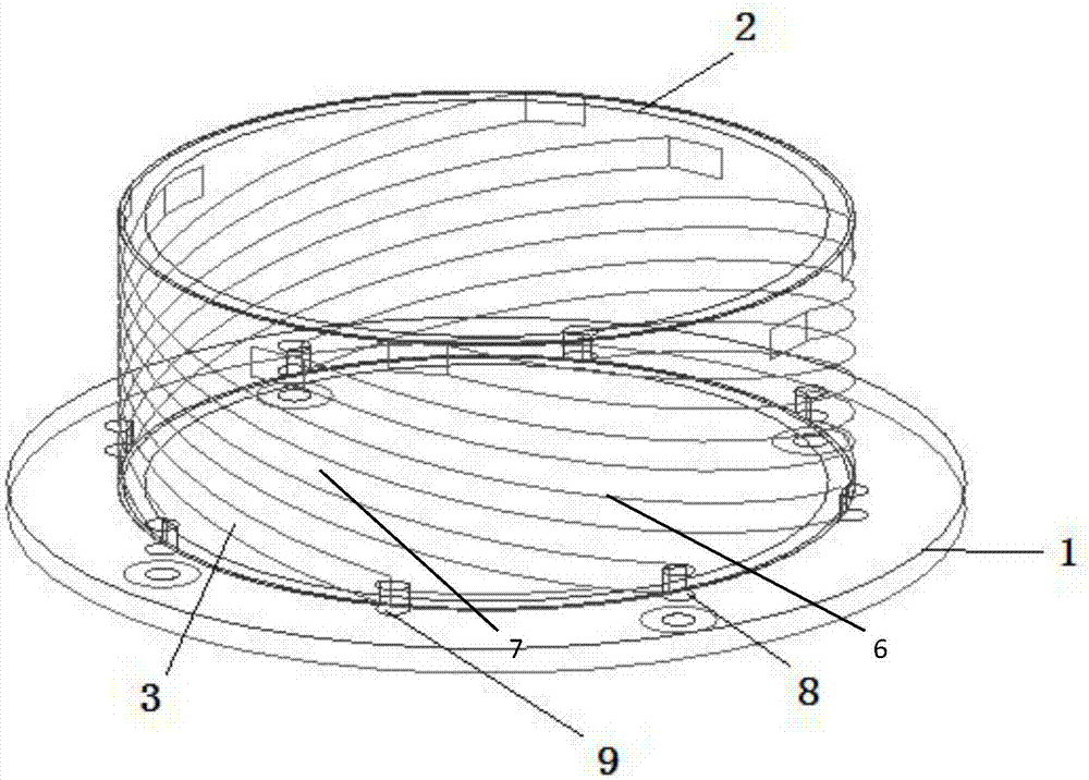
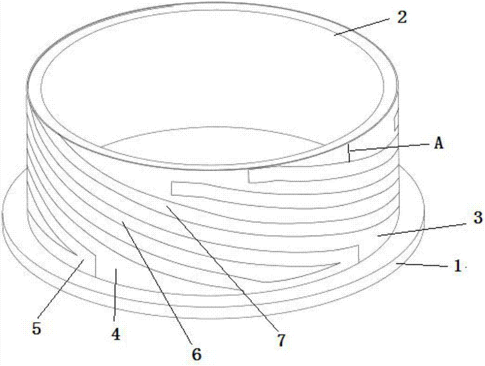
[0035] Refer to attached Figure 1-3 , a novel helical antenna provided by the present invention, comprising a feeding board 1 on which a supporting body 2 is arranged;

[0036] An antenna body 3 is pasted on the outer surface of the support body 2, the antenna body 3 includes a circuit board 4 and a plurality of radiation units 5, the circuit board 4 is pasted on the surface of the support body 2, the The circuit board 4 is printed with a number of radiation units 5 arranged in parallel. Since the circuit board 4 is attached to the surface of the support body 2, the radiation unit 5 is spirally wound on the support body 2 through the circuit board 4 to form a spiral antenna;

[0037] Specifically, the circuit board 4 is covered on the support body 2 , and at this time, the radiation unit on the circuit board 4 is equivalent to being wound on the support body 2 inside the circuit board 4 .

[0038] Further, the support body 2 is cut along a direction parallel to the feeder b...

Embodiment 2

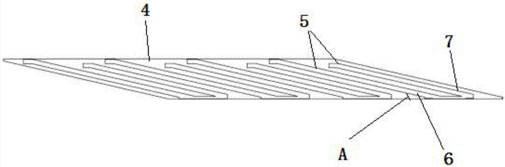
[0042] Refer to attached image 3 Further, the improvement of this embodiment is that each of the radiating units 5 includes a main radiating arm 6 and a secondary radiating arm 7 , and the width of the main radiating arm 6 is the same as that of the secondary radiating arm 7 .

[0043] In this embodiment, the addition of the auxiliary radiation arm 7 of the antenna can expand the bandwidth of the antenna due to the addition of a radiation arm 7, making the antenna electromagnetic energy radiation stronger and improving the antenna gain. Through the length of the main radiation arm 6 and the auxiliary radiation arm 7 Adjustment, the antenna can also work in dual-band.

[0044] Specifically, the main radiating arm 6 works at one frequency point, and the secondary radiating arm 7 works at another frequency point, and the respective lengths are adjusted. The two frequency points can be overlapped to increase the bandwidth, or two independent resonance points can be formed. Worki...

Embodiment 3

[0048] This embodiment is a further improvement on Embodiment 2. The main radiating arm 6 and the auxiliary radiating arm 7 are arranged in parallel, and the distance between the main radiating arm 6 and the auxiliary radiating arm 7 is the same as the width of the main radiating arm 6 . The typical arrangement of the main radiating arm 6 and the auxiliary radiating arm 7 has a lower antenna height and a smaller antenna diameter than a general low-profile planar quadrifilar helical antenna.

[0049] In this embodiment, the height of the antenna supporting body 2 is 10 mm, and the diameter of the antenna is 28 mm. In terms of height, it is far smaller than the existing four-arm helical antenna, with a smaller structure and lighter weight; and because of the low height, it does not need to occupy too much space when used, saving space and being convenient to use.

[0050] Further, among several radiation units 5 arranged in parallel, the distance between adjacent radiation units...


PUM


Abstract

The invention discloses a new-type helical antenna. The new-type helical antenna comprises a feeding panel; the feeding panel is provided with a supporting body; an antenna body is attached to the supporting body; the antenna body comprises a circuit board and a plurality of radiating elements; the circuit board is attached to the surface of the supporting body; the plurality of radiating elements arranged in parallel are printed on the circuit board, and the radiating elements are spirally wound on the supporting body to form the helical antenna; and the supporting body is cut along a direction parallel to the feeding panel to obtain a round cutting surface. The new-type helical antenna provided by the invention has the characteristics of being smaller in structure, lighter in quality, simple in production process and good in property.

Description

technical field [0001] The invention belongs to the technical field of antennas, and in particular relates to a novel helical antenna. Background technique [0002] Global Positioning System is the most widely used satellite navigation and positioning system today, mainly used in navigation, surveying and mapping, monitoring, timing, communication and other fields. In recent years, positioning technology has developed vigorously, especially in vehicle navigation and positioning of small mobile terminals. These applications have put forward higher and higher requirements for miniaturization, light weight, and high precision of antennas. [0003] The traditional helical antenna is made of copper wire or other metals, with complex processing technology, narrow bandwidth, poor consistency, high profile, and large phase error. Contents of the invention [0004] The technical problem to be solved by the present invention is to provide a high-precision four-arm helical antenna w...

Claims


Application Information

Patent Timeline
Patent Type & Authority Applications(China)
IPC IPC(8): H01Q1/38H01Q1/50H01Q7/02
CPCH01Q1/38H01Q1/50H01Q7/02
Inventor 初征陈琨云
Owner 西安巨向导航科技有限公司
Why Eureka
Try Eureka