A clutch device and a method for manufacturing the same

A clutch device and double clutch technology, applied in the direction of clutches, friction clutches, mechanically driven clutches, etc., can solve problems such as welding deformation, large tolerance range, and reduced rotor dimensional stability, and achieve the effect of dimensional stability

Active Publication Date: 2017-09-01
SCHAEFFLER TECH AG & CO KG
View PDF10 Cites 1 Cited by
  • Summary
  • Abstract
  • Description
  • Claims
  • Application Information

AI Technical Summary

Problems solved by technology

However, welding distortions can occur during welding, which result in large tolerance

Method used


Image

  • A clutch device and a method for manufacturing the same
  • A clutch device and a method for manufacturing the same
  • A clutch device and a method for manufacturing the same

Examples


Embodiment Construction

[0024] specific implementation plan

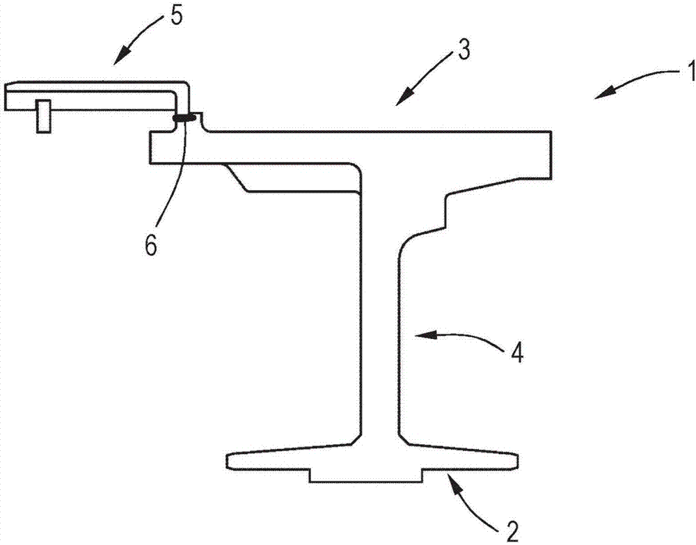
[0025] figure 1 The rotor 1 of a clutch arrangement, not shown in detail, according to a first exemplary embodiment is shown. The rotor 1 has a first section 2 and a second section 3 , which are connected to one another via intermediate webs 4 . In this case, the first section 2 and the second section 3 extend approximately parallel to the axis of rotation of the clutch device. It can be seen that the intermediate web 4 extends approximately perpendicular to the first section 2 and the second section 3 in a cross-sectional view. According to this exemplary embodiment, the rotor 1 is produced by spinning, so that the first section 2 , the second section 3 and the intermediate web 4 are formed in one piece with one another.

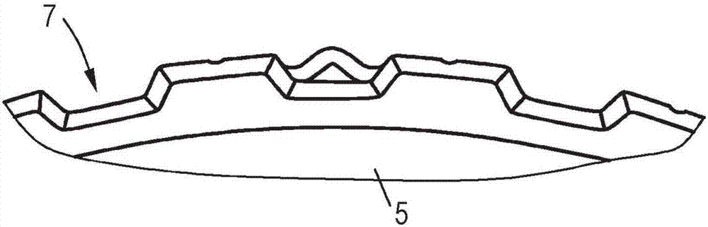
[0026] It is clear that the diaphragm holder 5 is connected to the rotor 1 , which according to the exemplary embodiment is connected to the rotor 1 by means of a welding method. The connection between rotor 1 and d...


PUM


Abstract

A clutch device and a method for manufacturing the same are disclosed. The clutch device includes a rotor (1, 8, 11, 14) and a film sheet carrier (5, 9, 12, 15) connected to the rotor (1, 8, 11, 14). The rotor (1, 8, 11, 14) is manufactured by forging or flow forming.

Description

technical field [0001] The invention relates to a clutch device, which includes a rotor and a diaphragm support connected with the rotor. Background technique [0002] As is known from the prior art, with such a clutch arrangement it is possible to connect the first and / or the second drive unit to the output shaft. The first drive unit can be, for example, an internal combustion engine, and the second drive unit can be an electric motor. In this case, the second drive unit acts on the radially surrounding rotor or transmits a drive force or torque to the rotor. The rotor is formed, for example, as part of the electric machine or is connected to the electric machine, so that the electric machine is coupled to the rotor, for example as an auxiliary motor. [0003] This type of rotor is usually manufactured by welding several individual parts. During welding, however, welding distortions can occur, which result in larger tolerance ranges, thereby reducing the dimensional sta...

Claims


Application Information

Patent Timeline
IPC IPC(8): F16D13/58B21D22/14B21K1/00
CPCB21D22/14B21K1/00F16D13/58B21D53/26B21H1/06B21K1/28F16D13/683F16D2250/00F16D2250/0023
Inventor 安德烈·施贝克艾尔玛·洛伦佐
Owner SCHAEFFLER TECH AG & CO KG
Why Eureka
Try Eureka