Mobile terminal and antenna switching method and antenna switching device thereof

A mobile terminal and antenna switching technology, which is applied in the direction of antenna support/installation device, antenna, antenna parts, etc., can solve the problems of inability to use a variety of different use environments and low flexibility

Inactive Publication Date: 2017-09-01
GUANGDONG OPPO MOBILE TELECOMM CORP LTD
9 Cites 21 Cited by

AI-Extracted Technical Summary

Problems solved by technology

[0003] In the prior art, each antenna of the mobile terminal works independently, the...

Method used

The antenna switching method of the above mobile terminal can realize the intelligent switching of the mobile terminal antenna, to make the optimal configuration to the use...

Abstract

The invention provides an antenna switching method and antenna switching device of a mobile terminal and the mobile terminal. The antenna switching method comprises the following steps: acquiring state information of the mobile terminal; selecting two antennae from an antenna group according to the state information; separately taking the two selected antennae as a main antenna and a diversity antenna; comparing the performance of the current master antenna and the current diversity antenna; and if the performance of the current master antenna is poorer than the performance of the current diversity antenna, performing antenna switching, taking the antenna with better performance as the master antenna, and taking the antenna with poorer performance as the diversity antenna. According to the antenna switching method, the antenna switching device and the mobile terminal provided by the invention, the intelligent switching of the antennae in the mobile terminal can be achieved, and the communication performance of the mobile terminal can be improved.

Application Domain

Spatial transmit diversityAntenna supports/mountings

Technology Topic

EngineeringDiversity scheme +1

Image

  • Mobile terminal and antenna switching method and antenna switching device thereof
  • Mobile terminal and antenna switching method and antenna switching device thereof
  • Mobile terminal and antenna switching method and antenna switching device thereof

Examples

  • Experimental program(1)

Example Embodiment

[0016] The technical solutions in the embodiments of the present invention will be clearly and completely described below in conjunction with the drawings in the embodiments of the present invention. It can be understood that the specific embodiments described here are only used to explain the present invention, but not to limit the present invention. In addition, it should be noted that, for ease of description, the drawings only show a part but not all of the structure related to the present invention. Based on the embodiments of the present invention, all other embodiments obtained by those of ordinary skill in the art without creative work shall fall within the protection scope of the present invention.
[0017] The mobile terminals provided by the embodiments of the present invention include electronic devices such as smart phones, tablet computers, smart wearable devices, digital audio and video players, e-readers, handheld game consoles, and in-vehicle electronic devices.
[0018] The terms "first", "second" and "third" in the present invention are only used for descriptive purposes, and cannot be understood as indicating or implying relative importance or implicitly indicating the number of indicated technical features. Therefore, the features defined with "first", "second", and "third" may explicitly or implicitly include at least one of the features. In the description of the present invention, "a plurality of" means at least two, such as two, three, etc., unless otherwise specifically defined. All directional indications (such as up, down, left, right, front, back...) in the embodiments of the present invention are only used to explain the relative positional relationship between the components in a specific posture (as shown in the drawings) , Movement, etc., if the specific posture changes, the directional indication will change accordingly. In addition, the terms "including" and "having" and any variations thereof are intended to cover non-exclusive inclusion. For example, a process, method, system, product, or device that includes a series of steps or units is not limited to the listed steps or units, but optionally includes unlisted steps or units, or optionally also includes Other steps or units inherent in these processes, methods, products or equipment.
[0019] Reference to "embodiments" herein means that a specific feature, structure, or characteristic described in conjunction with the embodiments may be included in at least one embodiment of the present invention. The appearance of the phrase in various places in the specification does not necessarily refer to the same embodiment, nor is it an independent or alternative embodiment mutually exclusive with other embodiments. Those skilled in the art clearly and implicitly understand that the embodiments described herein can be combined with other embodiments.
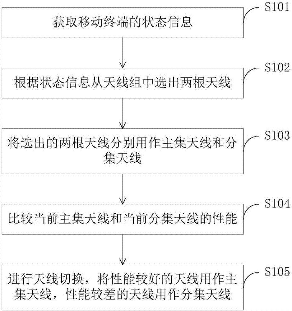
[0020] See figure 1 , figure 1 It is a schematic flowchart of an embodiment of an antenna switching method for a mobile terminal of the present invention. The invention can realize the switching between antennas in the mobile terminal to allocate antennas with different performances and select the antenna with the best performance as the main antenna. In the mobile terminal, the main antenna is used for transmitting and receiving signals, and the diversity antenna is used for receiving signals. The antennas in the mobile terminal applied in the antenna switching method of this embodiment constitute an antenna group, and the antenna group includes at least three antennas. The antenna switching method of this embodiment includes the following steps.
[0021] S101: Acquire status information of the mobile terminal.
[0022] The state information of the mobile terminal acquired in this step S101 may be about the environment where the mobile terminal is currently located, or may be about the current usage of the mobile terminal. Since the performance of the antenna in the mobile terminal is related to the status information of the mobile terminal, it is necessary to determine the quality of the antenna performance in the current state according to the status information.
[0023] This step S101 may be to obtain the frequency band information of the environment where the mobile terminal is located. If the frequency band information is a high frequency band, that is, when the mobile terminal is in a high frequency band cell, the performance of the high frequency antenna lower frequency band antenna is better; correspondingly, if the frequency band information is low frequency band , The performance of the low-frequency antenna and the higher-frequency antenna is better.
[0024] This step S101 may also be to obtain user operation information of the mobile terminal. For example, when an antenna exists in a part where the user holds the mobile terminal, the performance of the antenna in this part is worse than that in other parts.
[0025] The state information of the mobile terminal can be acquired by automatic sensing such as the mobile terminal's own sensors, or it can be acquired through autonomous input by the user.
[0026] S102: Select two antennas from the antenna group according to the status information.
[0027] As can be seen from the above description of step S101, according to the acquired state information, the performance of the antenna in the current state can be known. Therefore, in this step S102, two antennas with better performance are selected from the antenna group according to the state information.
[0028] If the antenna group of the mobile terminal includes a full-frequency antenna, a high-frequency antenna, and a low-frequency antenna, the frequency band information of the environment where the mobile terminal is located is acquired in step S101, the two antennas selected in this step S102 are full-frequency antennas, and according to High-frequency antenna or low-frequency antenna selected by frequency band information.
[0029] The above step S101 can also obtain user operation information of the mobile terminal. In this step S102, the degree to which the antenna in the antenna group is affected by the user operation can be determined according to the user operation information, and then the two antenna groups that are least affected by the user operation are selected from the antenna group antenna.
[0030] For example, for the case where the first antenna included in the antenna group is set at the top of the mobile terminal, the second antenna is set at the bottom left of the mobile terminal, and the third antenna is set at the bottom right of the mobile terminal, the user operation information obtained in step S101 Can hold information for users.
[0031] When the user's holding information is left-hand holding, it is considered that the left-hand holding has the greatest impact on the performance of the second antenna at the bottom left of the mobile terminal. Therefore, the first antenna and the third antenna are selected in step S102; when the user holding information is When holding with the right hand, holding with the right hand has the greatest impact on the performance of the third antenna at the bottom right of the mobile terminal, so the first antenna and the second antenna are selected in step S102.
[0032] S103: Use the two selected antennas as the main antenna and the diversity antenna respectively.
[0033] The two antennas selected in step S102 are respectively used as the main antenna and the diversity antenna. In this step, the selection of the main antenna and the diversity antenna can be randomly allocated or allocated according to the default priority, that is, the antenna with a higher priority is preferentially selected as the main antenna.
[0034] S104: Compare the performance of the current main antenna and the current diversity antenna.
[0035] After initially determining the main antenna and diversity antenna in step S103, compare the performance of the current main antenna and the current diversity antenna, and evaluate the performance of the current main antenna and diversity antenna to ensure that the antenna with the best performance is used as the main antenna antenna.
[0036] If the comparison result in this step S104 is that the current main antenna performance is better than the current diversity antenna performance, the current state is maintained without antenna switching; if the comparison result is that the current main antenna performance is worse than the current diversity antenna performance, then step S105.
[0037] S105: Perform antenna switching, and use the antenna with better performance as the main antenna, and the antenna with poor performance as the diversity antenna.
[0038] The above steps S104 and S105 realize the selection of the antenna with the best performance as the main antenna. In practical applications, the comparison of antenna performance in step S104 can be to compare the signal reception performance of the antenna when it is working, or to compare the antenna performance when it is working. Other properties. And the comparison process can be real-time or periodic.
[0039] In addition, the conditions for antenna switching can be further set as: when the performance of the current diversity antenna is better than the performance of the current main antenna to a certain extent, the antenna switching is performed, that is, the performance of the current diversity antenna is better than the performance of the current main antenna. When the predetermined level is not exceeded, antenna switching is not performed to reduce the cost of antenna switching.
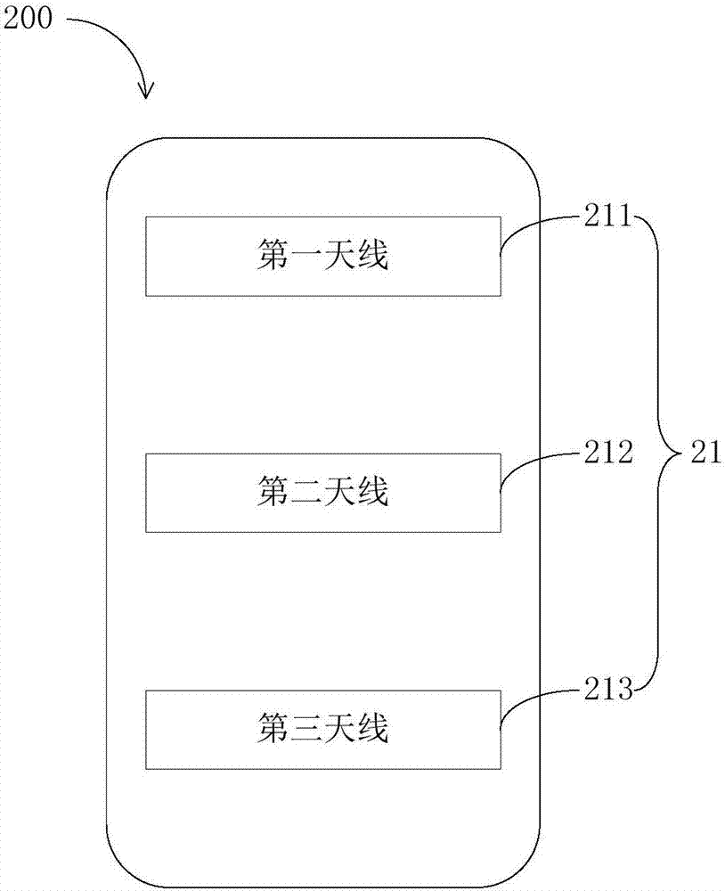
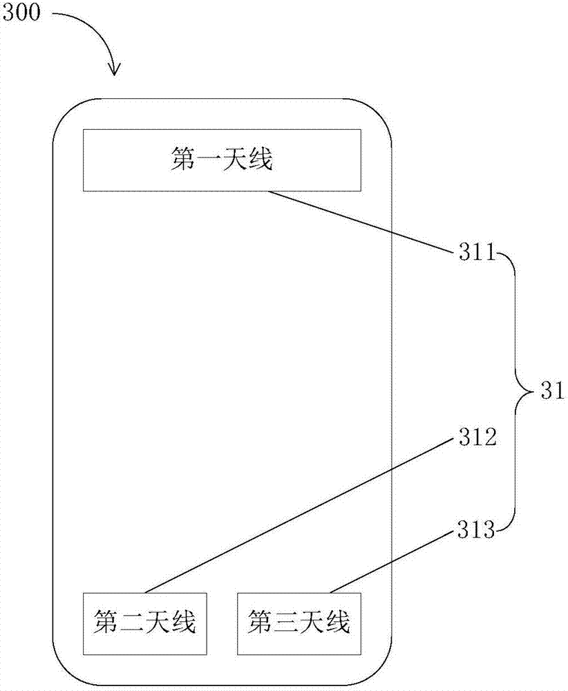
[0040] The above steps S101-S105 realize the intelligent switching of the antennas in the mobile terminal. The following takes the case where the mobile terminal includes three antennas as an example. The three antennas in the antenna group of the mobile terminal can be set at any position of the mobile terminal, such as figure 2 with image 3 As shown, figure 2 Yes figure 1 A schematic structural diagram of a mobile terminal in an embodiment of the antenna switching method shown, image 3 Yes figure 1 Another schematic diagram of the structure of the mobile terminal in an embodiment of the antenna switching method is shown.
[0041] in figure 2 Here, the mobile terminal 200 includes an antenna group 21, and the antenna group 21 includes a first antenna 211, a second antenna 212, and a third antenna 213. Among them, the first antenna 211 is arranged on the top of the mobile terminal 200, the second antenna 212 is arranged on the middle of the mobile terminal 200, and the third antenna 213 is arranged on the bottom of the mobile terminal 200.
[0042] Further, if the first antenna 211 is a full-frequency antenna, the second antenna 212 is a high-frequency antenna, and the third antenna 213 is a low-frequency antenna, the high-frequency antenna and the low-frequency antenna are relative concepts, for example, it may be a high-frequency antenna above 1 GHz. , Below 1GHz is a low-frequency antenna; it can also be a high-frequency antenna above 2GHz, and a low-frequency antenna below 2GHz.
[0043] For intelligent switching of a full-frequency antenna, a high-frequency antenna, and a low-frequency antenna, the antenna switching method of the foregoing embodiment can be applied. In step S101, the frequency band information of the environment where the mobile terminal is located is obtained; if the frequency band information of the environment where the mobile terminal is located is a high frequency band, then a full frequency antenna and a high frequency antenna are selected in step S102; if the frequency band information of the environment where the mobile terminal is located is a low frequency band, In step S103, a full-frequency antenna and a low-frequency antenna are selected.
[0044] in image 3 In this case, the mobile terminal 300 includes an antenna group 31, and the antenna group 31 includes a first antenna 311, a second antenna 312, and a third antenna 313. The first antenna 311 is disposed on the top of the mobile terminal 300, the second antenna 312 is disposed on the bottom left side of the mobile terminal 300, and the third antenna 313 is disposed on the bottom right side of the mobile terminal 300.
[0045] For the antenna switching of the mobile terminal 300, the antenna switching method of the above-mentioned embodiment can also be applied to obtain the user's holding information in step S101; if the user's holding information is left-handed, the first antenna 311 and the first antenna are selected in step S102. The third antenna 313; if the user's holding information is right-hand holding, the first antenna 311 and the second antenna 312 are selected in step S102.
[0046] for image 3 In the mobile terminal 300 shown, the first antenna 311 may also be a full-frequency antenna, the second antenna 312 is a high-frequency antenna, and the third antenna 313 is a low-frequency antenna.
[0047] It should be noted that the high-frequency antenna and the low-frequency antenna described above may be two parts of one antenna in physical structure, that is, the high-frequency antenna and the low-frequency antenna may be located at the bottom of the mobile terminal together. Therefore, for an antenna group of a mobile terminal including a full-frequency antenna, a high-frequency antenna, and a low-frequency antenna, the antenna group may have only two antennas in a physical sense, but in a functional sense, it is considered that there are three antennas.
[0048] The antenna switching method of the above mobile terminal can realize the intelligent switching of the mobile terminal antenna to make the optimal configuration for the use of the antenna, and select the antenna with better performance as the main antenna and the diversity antenna to optimize the communication capability of the mobile terminal.
[0049] When applying the above-mentioned antenna switching method of a mobile terminal, an executable program is usually used to represent its logical process, that is, each step of the antenna switching method, and a software system is constructed based on hardware equipment to run the executable program to realize the antenna switching method .
[0050] For the executable program, it is stored in a computer storage medium, which can be a floppy disk, hard disk, optical disk, memory card, etc., which can be read and written through an interface connection; it can also be a server, which can be read and written through a network connection. The executable program can be read and executed to implement the steps in the antenna switching method of the mobile terminal in the above embodiment.
[0051] For the software system, multiple modules are constructed in the mobile terminal of the present invention to implement multiple steps in the antenna switching method. Please refer to Figure 4 , Figure 4 It is a schematic structural diagram of a software system of an embodiment of an antenna switching device for a mobile terminal of the present invention; the antenna switching device 400 of this embodiment includes an acquisition module 41, a selection module 42, a comparison module 43, and a switching module 44.
[0052] The acquisition module 41 is used to acquire the status information of the mobile terminal; the selection module 42 selects two antennas from the antenna group of the mobile terminal according to the status information; the selected two antennas are respectively used as the main antenna and the diversity through the switching module 44 Antenna; the comparison module 43 compares the performance of the current main antenna and the current diversity antenna; if the performance of the current main antenna is worse than the performance of the current diversity antenna, the antenna switch is performed through the switching module 44 to use the better performance antenna As the main antenna, the antenna with poor performance is used as the diversity antenna.
[0053] Each module of the antenna switching device 400 of this embodiment can implement the antenna switching method of the foregoing embodiment, and details are not repeated here.
[0054] For hardware equipment, the antenna switching device 400 includes a processor 51, please refer to Figure 5 , Figure 5 It is a schematic diagram of the structure of the hardware device of an embodiment of the antenna switching device of the mobile terminal of the present invention.
[0055] The processor 51 can obtain the status information of the mobile terminal, select two antennas from the antenna group of the mobile terminal according to the status information, and use the two antennas as the main antenna and the diversity antenna respectively. The processor 51 can also compare the performance of the current main antenna and the current diversity antenna when the main antenna and the diversity antenna are working; to switch the antenna when the performance of the current main antenna is worse than the performance of the current diversity antenna to compare the performance. The good antenna is used as the main antenna, and the poorer performance antenna is used as the diversity antenna.
[0056] The antenna switching device 400 may also include a memory 52 for storage support during the operation of the processor 51. The memory 52 may be a device of the antenna switching device 400 itself, or a memory in the mobile terminal, or a memory externally connected to the mobile terminal.
[0057] The antenna switching device 400 of this embodiment is used in a mobile terminal to realize intelligent switching of antennas in the mobile terminal and improve the communication performance of the mobile terminal.
[0058] For mobile terminals that can implement the above antenna switching method, there are multiple structures. Three embodiments are given below. For details, please refer to Figure 6-Figure 8 , Image 6 Is a schematic structural diagram of an embodiment of a mobile terminal of the present invention, Figure 7 Is a schematic structural diagram of another embodiment of a mobile terminal of the present invention, Figure 8 It is a schematic structural diagram of another embodiment of the mobile terminal of the present invention.
[0059] Image 6 The mobile terminal 600 in the embodiment in FIG. 2 includes an antenna group 61, an antenna switch 62, and a processor 63. The antenna group 61 includes at least three antennas, and the antenna switch 62 is connected to the antenna group 61 and the processor 63 respectively.
[0060] When the mobile terminal 600 performs antenna switching in this embodiment, the processor 63 obtains the status information of the mobile terminal 600, and selects two antennas from the antenna group 61 according to the status information; the selected two antennas are switched through the antenna switch 62 Used as the main antenna and the diversity antenna respectively; the processor 63 compares the performance of the current main antenna and the current diversity antenna, if the current main antenna performance is worse than the current diversity antenna performance, the antenna switch 62 is used to switch the antenna through the antenna switch 62 The antenna with better performance is used as the main antenna, and the antenna with poor performance is used as the diversity antenna. In this way, the mobile terminal 600 can achieve better communication performance.
[0061] Figure 7 The mobile terminal 700 in the embodiment in FIG. 1 includes an antenna group 71, an antenna switch 72, and a processor 73.
[0062] The antenna group 71 includes a full-frequency antenna 711, a high-frequency antenna 712, and a low-frequency antenna 713. The full-frequency antenna 711 is located on the top of the mobile terminal 700. The high-frequency antenna 712 and the low-frequency antenna 713 are both located at the bottom of the mobile terminal 700. The structure is two parts of an antenna. The antenna switch 72 is a double pole three throw switch. The mobile terminal 700 further includes a main antenna terminal 74 and a diversity antenna terminal 75.
[0063] When the mobile terminal 700 performs antenna switching in this embodiment, the processor 73 obtains the frequency band information of the environment where the mobile terminal 700 is located. If the frequency band information is high frequency information, the processor 73 selects the full frequency antenna 711 and the high frequency antenna 712 as For the main antenna and the diversity antenna, the full-frequency antenna 711 is the main antenna by default, and the high-frequency antenna 712 is the diversity antenna; if the frequency band information is low-frequency information, the processor 73 performs similar operations, and details are not repeated here.
[0064] The processor 73 further compares the performance of the current main antenna and the current diversity antenna. If the performance of the current main antenna is worse than the performance of the current diversity antenna, the antenna switch 72 is used for antenna switching, and the antenna switch 72 uses the better performance antenna as The main antenna, the poorer performance antenna is used as the diversity antenna. In this way, the mobile terminal 700 can achieve better communication performance.
[0065] Figure 8 The mobile terminal 800 in the embodiment in FIG. 2 includes an antenna group 81, an antenna switch 82, and a processor 83.
[0066] The antenna group 81 includes a first antenna 811, a second antenna 812, and a third antenna 813. The first antenna 811 is arranged on the top of the mobile terminal 800, the second antenna 812 is arranged on the bottom left side of the mobile terminal 800, and the third antenna 813 is arranged On the bottom right side of the mobile terminal 800. The antenna switch 82 is a double pole three throw switch. The mobile terminal 800 further includes a main antenna terminal 84 and a diversity antenna terminal 85.
[0067] When the mobile terminal 800 performs antenna switching in this embodiment, the processor 83 obtains the user's holding information of the mobile terminal 800. If the user's holding information is left-handed, the processor 83 selects the first antenna 811 and the third antenna 813, respectively Used as the main antenna and the diversity antenna, the first antenna 811 can be defaulted as the main antenna, and the third antenna 813 is the diversity antenna; if the user holds the information with the right hand, the processor 83 performs the same operation, and the details are not repeated.
[0068] The processor 83 further compares the performance of the current main antenna and the current diversity antenna. If the performance of the current main antenna is worse than the performance of the current diversity antenna, the antenna switch 82 is used to switch the antenna, and the antenna switch 82 uses the better performance antenna as The main antenna, the poorer performance antenna is used as the diversity antenna. In this way, the mobile terminal 800 can achieve better communication performance.
[0069] The above are only the embodiments of the present invention, and do not limit the scope of the present invention. Any equivalent structure or equivalent process transformation made by using the content of the description and drawings of the present invention, or directly or indirectly applied to other related technologies In the same way, all fields are included in the scope of patent protection of the present invention.

PUM

no PUM

Description & Claims & Application Information

We can also present the details of the Description, Claims and Application information to help users get a comprehensive understanding of the technical details of the patent, such as background art, summary of invention, brief description of drawings, description of embodiments, and other original content. On the other hand, users can also determine the specific scope of protection of the technology through the list of claims; as well as understand the changes in the life cycle of the technology with the presentation of the patent timeline. Login to view more.
Why Eureka
Try Eureka