Sickbed capable of automatic mattress replacing
A mattress and automatic technology, applied in the field of medical machinery, can solve the problems that it cannot be used as a hospital bed, and people cannot lie on the hospital bed.
- Summary
- Abstract
- Description
- Claims
- Application Information
AI Technical Summary
Problems solved by technology
Method used
Image

Examples
Embodiment 1
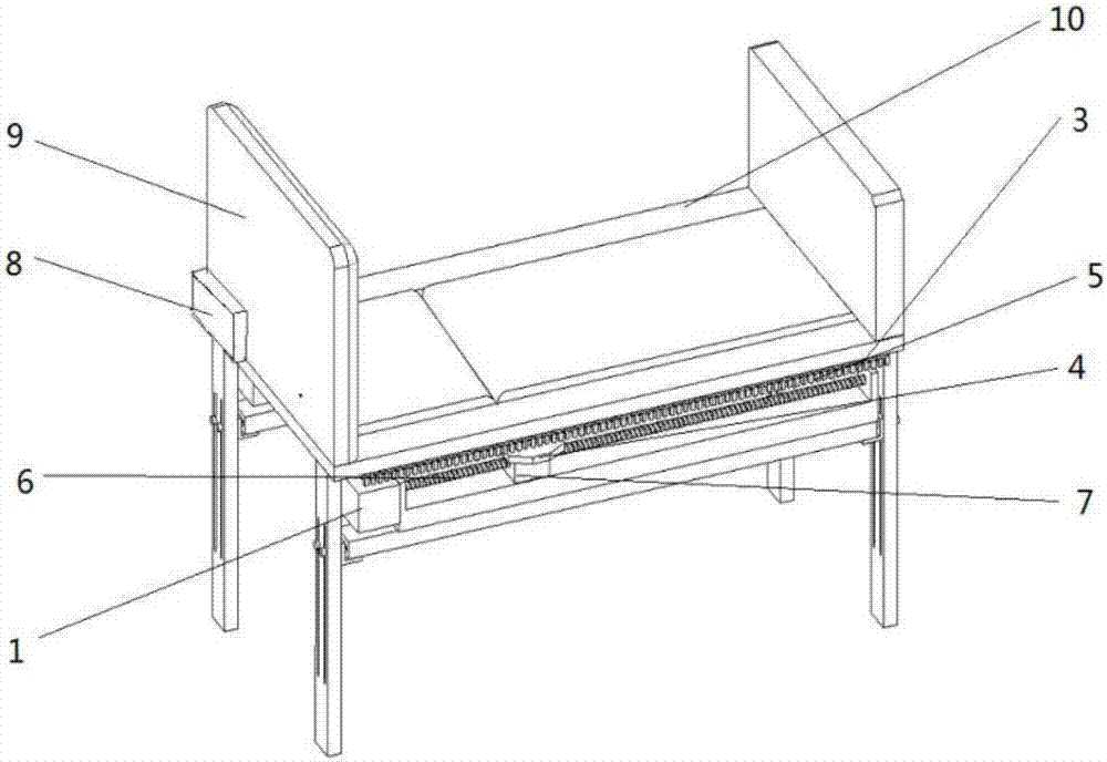
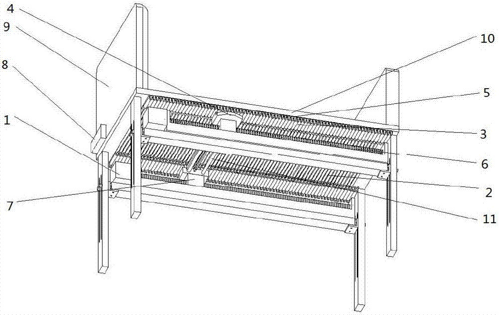
[0042] A bed that can automatically change the mattress, the core part of which is to change the mattress is a wedge-shaped slider 4 fixed on the base of the screw, and a support mechanism that supports the crawler-type support plate 2 composed of a support shaft 11. The support mechanism is composed of wedge-shaped sliders. Block 4 is made up of supporting shaft 11 structure. The purpose of this implementation case is to select the appropriate distance between the support shafts.
[0043] In this implementation case, four different spacings are selected: 4cm, 4.5cm, 5cm, and 5.5mm. After installation, the mattresses are changed for comparison. After the experiment, the mattresses of 4.5cm and 5cm are effective, and the gaps will not be cut when changing the mattresses. Small; while the spacing of 4cm is too small, the quilts are easy to be squeezed together without being replaced alternately, and the spacing of 5.5cm is too large. Therefore, the present invention should choo...
Embodiment 2
[0045] The purpose of this embodiment is to select a suitable installation position of the wedge-shaped slider 4 .
[0046] The wedge mechanism can be self-locking in both directions of motion transmission. When the wedge is the active part, the geometric size and the friction angle determine the self-locking condition; when the top column is the active part, only the friction angle determines the self-locking condition. The double-wedge angle wedge mechanism can not only realize large stroke ratio, boost ratio and high transmission efficiency, but also realize self-locking after the workpiece is clamped by the top column. In addition, it can also be designed according to the efficiency condition. The double-wedge angle oblique wedge mechanism is indeed a clamping mechanism with superior transmission and self-locking performance.
[0047] When the cooperation between the wedge-shaped slider and the support pin reaches the limit position, the support pin should be fully retract...
Embodiment 3
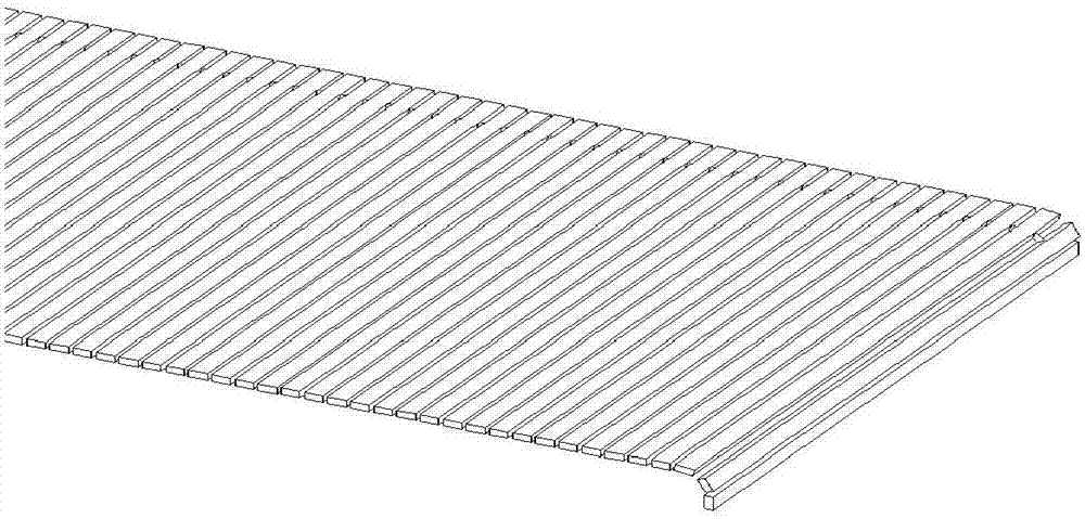
[0049] It is also very important to choose the spacing of the support pins 3, and this embodiment is to find out a more suitable position through experiments.
[0050] In this embodiment, three groups of different experiments are set up. Each supporting pin is placed 1cm, 2cm, 3cm apart respectively. One group is 1cm apart, with a 10x10x20mm linear guide groove in the middle to fix the pull-out force end of the support pin; the other set is 2cm apart, and a 10x20x20mm linear guide is used to fix the pull-out force end of the support pin; In the middle of 3cm, a 10x30x20mm linear guide groove is used to fix the pull-out end of the support pin. Experimental results show that the first set of intervals is too small, and the force driven by the motor needs to be too large; the second set of intervals is moderate enough that the mattresses on both sides can alternately go up and down; the third set of intervals is too large to fully support the crawler support plate. Therefore, t...
PUM
| Property | Measurement | Unit |
|---|---|---|
| Thickness | aaaaa | aaaaa |
| Bottom length | aaaaa | aaaaa |
| Thickness | aaaaa | aaaaa |
Abstract
Description
Claims
Application Information
 - R&D Engineer
- R&D Manager
- IP Professional
- Industry Leading Data Capabilities
- Powerful AI technology
- Patent DNA Extraction
Browse by: Latest US Patents, China's latest patents, Technical Efficacy Thesaurus, Application Domain, Technology Topic.
© 2024 PatSnap. All rights reserved.Legal|Privacy policy|Modern Slavery Act Transparency Statement|Sitemap