Permanent magnet suspension train track system

A magnetic levitation and rail technology, applied in the field of rail transportation, can solve the problems of wheel bearing wear, derailment of the open wheel-rail structure, high operation and maintenance costs, and achieve the effect of slight contact force of the wheels

Active Publication Date: 2017-09-22
DALIAN WHIM SCI & TECH LTD CO
View PDF8 Cites 12 Cited by
  • Summary
  • Abstract
  • Description
  • Claims
  • Application Information

AI Technical Summary

Problems solved by technology

[0002] The main problems in the existing technology are: EMS electromagnetic levitation system and electromagnetic guidance system require complex active control system, the weight of the train is high, energy consumption is high, and the structure is complex
The superconducting electric levitation train adopts the low-temperature superconducting system to levitate, there is obvious electromagnetic radiation, the structure is more complex, and at the same time, rubber wheels are needed for support at low speed, and the cost is higher
Medium and low-speed maglev trains are simple in structure, but the energy consumption of suspension is high. Linear asynchronous induction motors are used. Copper or aluminum plates are laid on the top surface of the track and the driving efficiency of asynchronous motors on the bottom of the train is very low.
[0003] The wheel-rail train has a simple structure and a long history of application, but the open wheel-rail structure may cause potential safety hazards of derailment at any time. In addition, the wheel bearings are severely worn under high speed and heavy loads, requiring frequent replacement and maintenance, high energy consumption, and low service life. The adhesion coefficient is low at high speed, and the transmission and deceleration are difficult. Although the one-time infrastructure cost is low, the later operation and maintenance cost is high

Method used


Image

  • Permanent magnet suspension train track system
  • Permanent magnet suspension train track system
  • Permanent magnet suspension train track system

Examples


Embodiment Construction

[0090] In order to make the purpose, technical solutions and advantages of the embodiments of the present invention clearer, the technical solutions in the embodiments of the present invention will be clearly and completely described below in conjunction with the drawings in the embodiments of the present invention. Obviously, the described embodiments It is a part of embodiments of the present invention, but not all embodiments. Based on the embodiments of the present invention, all other embodiments obtained by persons of ordinary skill in the art without making creative efforts belong to the protection scope of the present invention.

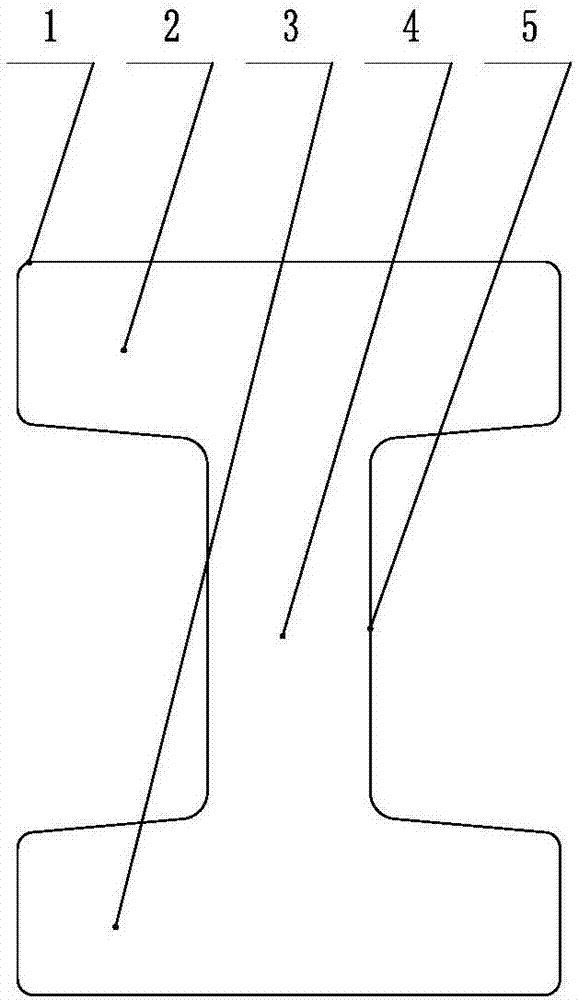
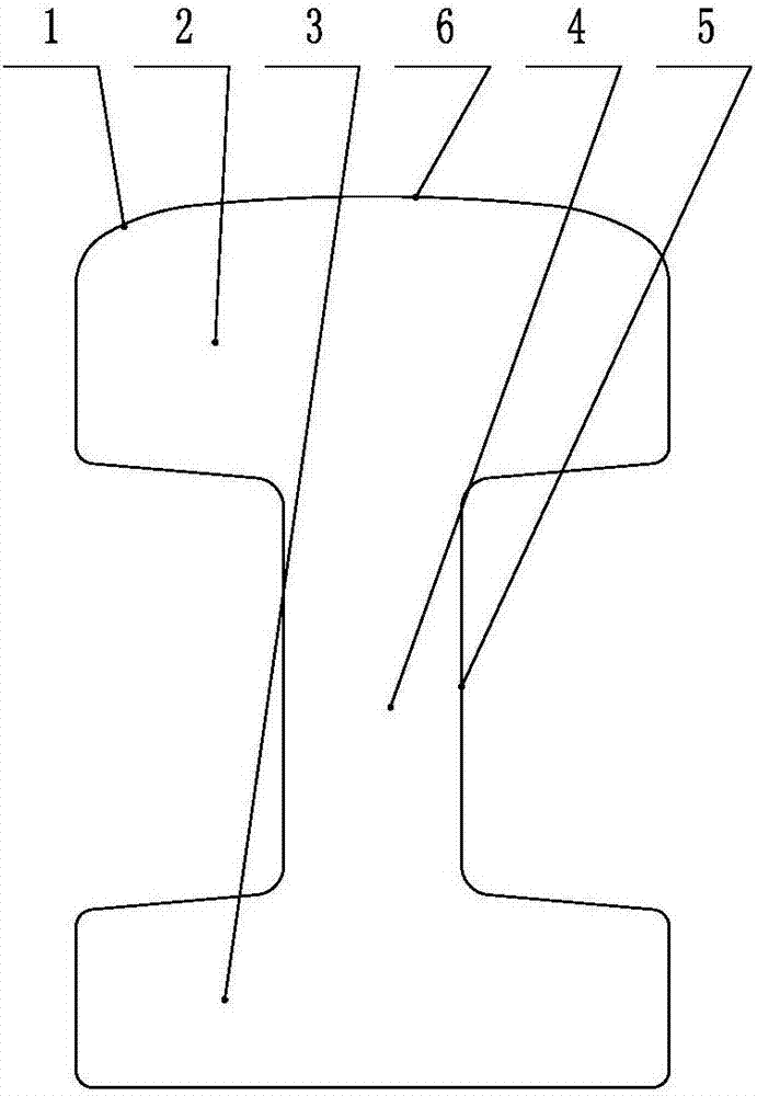
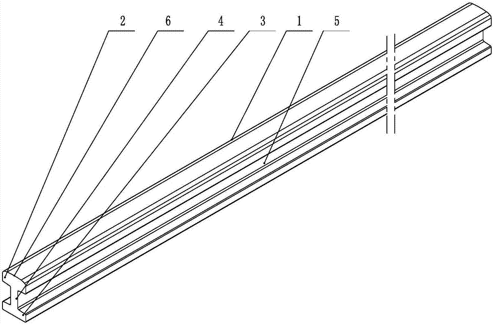
[0091] Such as figure 1 and image 3 As shown, a kind of I-shaped suspension rail 1, the overall section is I-shaped, and its material is a magnetic material, such as industrial pure iron or steel, and the I-shaped suspension rail 1 is composed of an upper yoke plate 2 and a lower yoke plate 3 The waist plate 4 vertically arranged in the mi...


PUM


Abstract

The invention provides a permanent magnet suspension train track system, specifically discloses a permanent magnet suspension track system, which is formed by suspension steel rails, a permanent magnet suspension track and permanent magnet suspension components, and introduces a permanent magnet suspension train system, which is formed in such a way that a train runs on the permanent magnet suspension track system, wherein the permanent magnet suspension track is arranged by using the suspension steel rails, and the permanent magnet suspension components are arranged on two sides of the suspension steel rails. The permanent magnet suspension components comprise upper magnetism collection boards, lower magnetism collection boards and suspension permanent magnets; and the magnetic gap between the permanent magnet suspension components is equal to the magnetic gaps between the left end surfaces and the right end surfaces of upper and lower yoke plates of the suspension steel rails. When the train matches with the track to run in a suspended manner, a bilateral permanent magnet linear motor efficient tractor train is formed by horizontal guide wheels, a traction coil of linear motor and a traction permanent magnet to build a safe, ultra high-speed and energy-saving novel rail transit system, wherein the horizontal guide wheels are arranged on the left side and the right side of the train, the traction coil of the linear motor is arranged on the track and the traction permanent magnet is arranged on the train. The permanent magnet suspension train track system has the advantages that automatic balancing passive suspension can be achieved, the traction driving efficiency is high, the cost is low, the permanent magnet suspension train track system is economic and energy-saving, the service life of the track is long, the permanent magnet suspension train track system is convenient to mount and adjust, and the permanent magnet suspension train track system is compatible with the existing wheel-rail track and is much safer than the existing wheel-rail track.

Description

technical field [0001] The invention relates to the technical field of rail transportation, in particular to a permanent maglev train rail system, especially for medium and low-speed subways and urban rapid rail transit systems, and vacuum pipeline ultra-high-speed trains and rail systems. Background technique [0002] The main problems existing in the prior art are: the EMS electromagnetic levitation system and the electromagnetic guidance system require complex active control systems, the weight of the train is high, the energy consumption is high, and the structure is complex. The superconducting electric levitation train adopts the low-temperature superconducting system to levitate, which has obvious electromagnetic radiation, and the structure is more complicated. At the same time, rubber wheels are required for support at low speeds, and the cost is higher. Medium and low-speed maglev trains have a simple structure, but high energy consumption for levitation. Linear as...

Claims


Application Information

Patent Timeline
Patent Type & Authority Applications(China)
IPC IPC(8): E01B25/30
CPCB60L13/04E01B25/30E01B25/305
Inventor 刘忠臣
Owner DALIAN WHIM SCI & TECH LTD CO
Why Eureka
Try Eureka