Symmetric permanent-magnetic suspension system and permanent-magnetic suspension train rail system

A magnetic levitation and symmetrical technology, applied in the field of rail transit, can solve the problems of derailment of open wheel-rail structure, wear of wheel bearings, high energy consumption of suspension, etc.

Active Publication Date: 2016-10-12
DALIAN WHIM SCI & TECH LTD CO
View PDF6 Cites 8 Cited by
  • Summary
  • Abstract
  • Description
  • Claims
  • Application Information

AI Technical Summary

Problems solved by technology

[0002] The main problems in the existing technology are: EMS electromagnetic levitation system and electromagnetic guidance system require complex active control system, the weight of the train is high, energy consumption is high, and the structure is complex
The superconducting electric levitation train adopts the low-temperature superconducting system to levitate, there is obvious electromagnetic radiation, the structure is more complex, and at the same time, rubber wheels are needed for support at low speed, and the cost is higher
Medium and low-speed maglev trains are simple in structure, but the energy consumption of suspension is high. Linear asynchronous induction motors are used. Copper or

Method used


Image

  • Symmetric permanent-magnetic suspension system and permanent-magnetic suspension train rail system
  • Symmetric permanent-magnetic suspension system and permanent-magnetic suspension train rail system
  • Symmetric permanent-magnetic suspension system and permanent-magnetic suspension train rail system

Examples


Example Embodiment

[0118] The present invention is described in further detail now in conjunction with accompanying drawing.

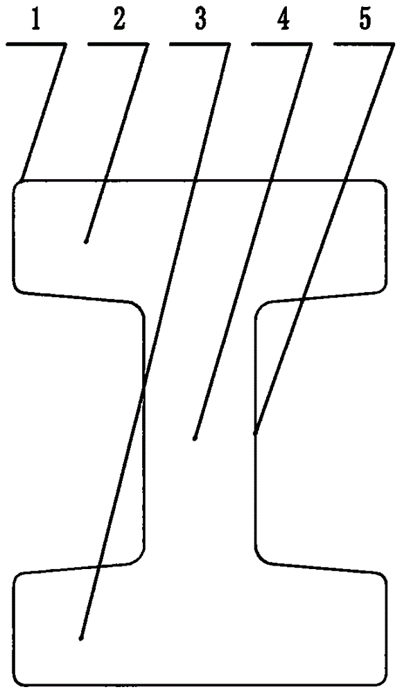
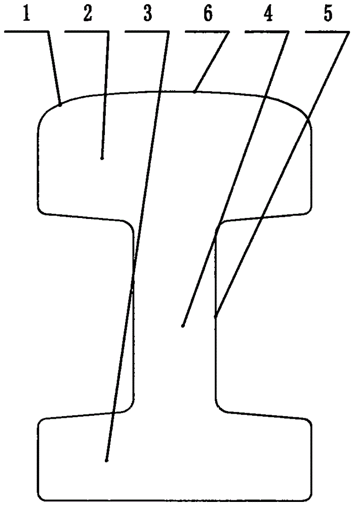
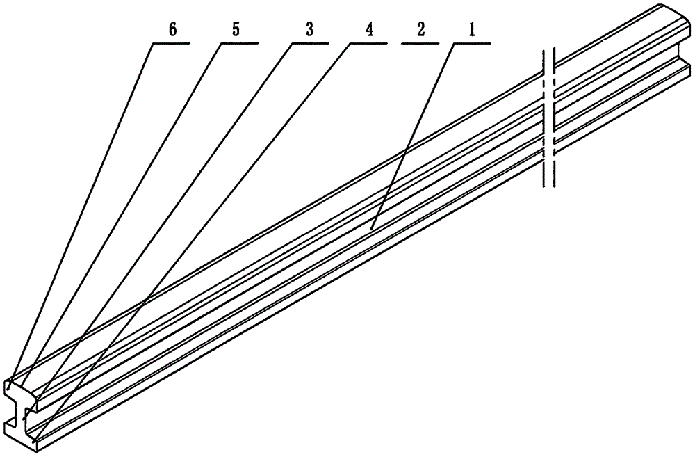
[0119] like figure 1 and image 3 As shown, a kind of I-shaped suspension rail 1, the overall section is I-shaped, and its material is a magnetic material, such as industrial pure iron or steel, and the I-shaped suspension rail 1 is composed of an upper yoke plate 2 and a lower yoke plate 3 The waist plate 4 vertically arranged in the middle is composed of the waist plate 4, which connects the upper yoke plate 2 and the lower yoke plate 3 in the middle. The left and right width and thickness are basically equal, and the section is extended along a straight line or a curve.

[0120] The left and right widths of the upper yoke plate 2 and the lower yoke plate 3 can also be unequal widths, and the thicknesses can also be unequal thicknesses.

[0121] The horizontal upper yoke plate 2 and the lower yoke plate 3 can be provided with a slope for ease of manufacture, prefera...


PUM


Abstract

The invention provides a symmetric permanent-magnetic suspension system and a permanent-magnetic suspension train rail system. The symmetric permanent-magnetic suspension system is characterized in that I-shaped suspension steel rails 1 made of a magnetic conductive material are arranged in the middle of the system; permanent-magnetic suspension assemblies 15 are symmetrically arranged on two sides of each I-shaped suspension steel rail 1; each permanent-magnetic suspension assembly 15 comprises an upper magnetism collection plate 12, a lower magnetism collection plate 14 and a suspension permanent magnet 13 arranged between the upper magnetism collection plate 12 and the lower magnetism collection plate 14; the magnetic gap of left and right end faces of the upper magnetism collection plates 12 and the lower magnetism collection plates 14 of left and right permanent-magnetic suspension assemblies is equal to that of left and right end faces of the upper yoke plates 2 and lower yoke plates 3 of the I-shaped steel rails 1, and upper and lower directions of the upper and lower magnetism collection plates and upper and lower yoke plates are staggered at a certain interval, so that passive suspension can be realized; left and right I-shaped suspension steel rails 1 are arranged at two ends of a sleeper 11, horizontal guide wheels (8) are arranged on left and right sides of a train; linear motor driving coils (8) are arranged on the rail, and form a two-sided permanent-magnetic linear motor high-efficiency traction train with a traction permanent-magnet on the train, and a safe, superspeed and energy-saving novel rail transition system is constructed.

Description

Technical field [0001] The invention relates to the technical field of rail transportation, in particular to a permanent magnetic levitation rail system, especially for medium and low-speed subways and urban rapid rail transit systems, vacuum pipeline ultra-high-speed trains and rail systems. Background technique [0002] The main problems existing in the prior art are: the EMS electromagnetic levitation system and the electromagnetic guidance system require complex active control systems, the weight of the train is high, the energy consumption is high, and the structure is complex. The superconducting electric levitation train adopts the low-temperature superconducting system to levitate, which has obvious electromagnetic radiation, and the structure is more complicated. At the same time, rubber wheels are required for support at low speeds, and the cost is higher. Medium and low-speed maglev trains have a simple structure, but high energy consumption for levitation. Linear...

Claims


Application Information

Patent Timeline
IPC IPC(8): E01B25/30B60L13/04
CPCB60L13/04E01B25/30E01B25/305
Inventor 刘忠臣
Owner DALIAN WHIM SCI & TECH LTD CO
Why Eureka
Try Eureka