Two-dimensional permanent magnet array type magnetic suspension gravity compensator

A permanent magnet array and gravity compensation technology, applied in the field of magnetic levitation, can solve problems such as large parasitic force and complex system structure, and achieve the effects of various forms, large optimization space, and easy implementation.

Active Publication Date: 2020-03-13
HARBIN INST OF TECH
View PDF3 Cites 1 Cited by
  • Summary
  • Abstract
  • Description
  • Claims
  • Application Information

AI Technical Summary

Problems solved by technology

[0003] The purpose of the present invention is to solve the problem of large parasitic force and complex system structure in the suspension mode or air flotation mode for gravity unloading of large load non-contact support, and provides a two-dimensional permanent magnet array type magnetic levitation gravity compensator

Method used


Image

  • Two-dimensional permanent magnet array type magnetic suspension gravity compensator
  • Two-dimensional permanent magnet array type magnetic suspension gravity compensator
  • Two-dimensional permanent magnet array type magnetic suspension gravity compensator

Examples


Embodiment 1

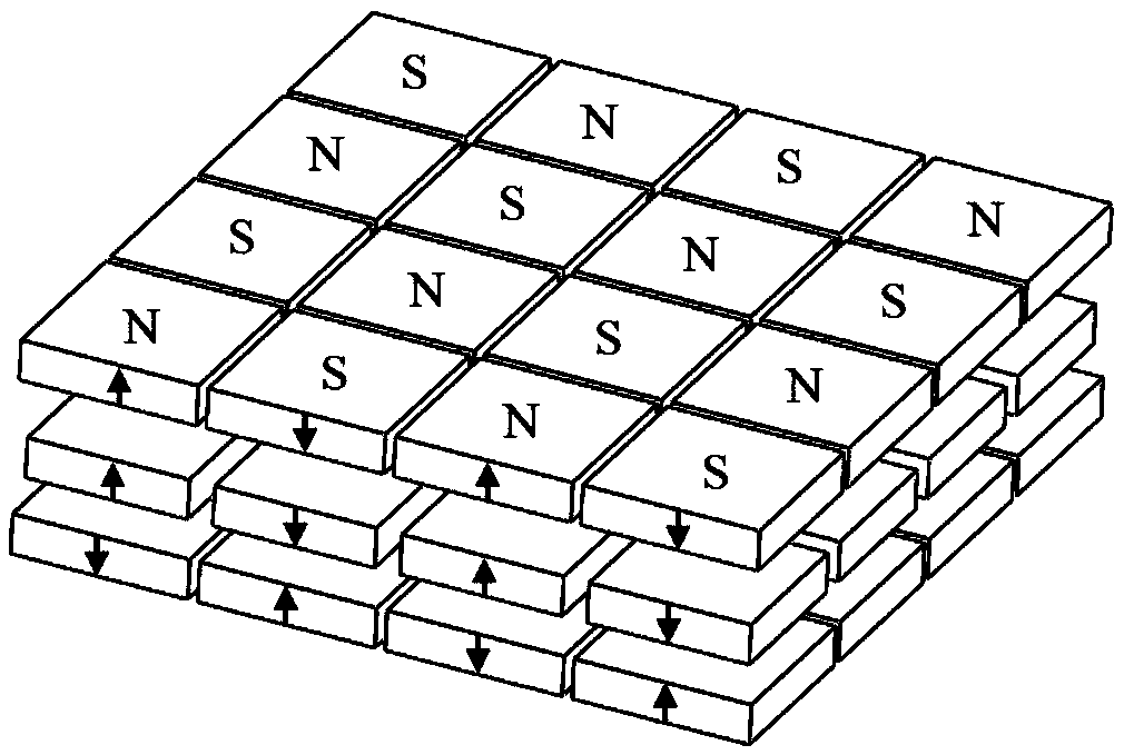
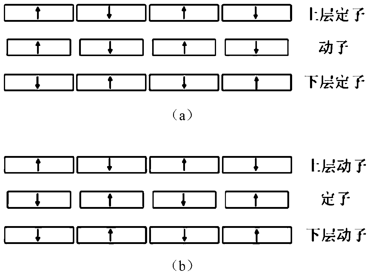
[0028] Embodiment one: see figure 1 , figure 2 with image 3 , the two-dimensional permanent magnet array magnetic levitation gravity compensator comprises a stator and a mover, and the compensator of the present embodiment is divided into a single mover (see figure 2 (a) shown) or single stator (see figure 2 (b) shown).

[0029] The first single mover compensator (see figure 2 As shown in (a): The stator includes an upper stator and a lower stator, and a mover is arranged between the upper stator and the lower stator that are parallel and fixedly connected to each other, and there is a vertical air gap between the two-layer stator and the mover; the two-layer stator and the The mover is a two-dimensional array plate structure composed of N×N rectangular permanent magnets, and there is an interval between any two adjacent permanent magnets in each plate structure;

[0030] The magnetization direction of the permanent magnet is vertical, and the magnetization direction...

Embodiment 2

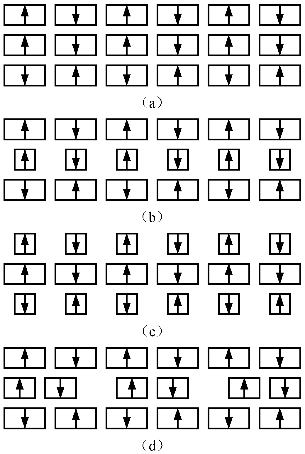
[0037] Embodiment two: see Figure 4 to Figure 6 To illustrate, the stator of the two-dimensional permanent magnet array magnetic levitation gravity compensator includes an upper stator and a lower stator that are parallel to each other and are fixedly connected, and the mover includes an upper mover and a lower mover that are parallel to each other and are fixedly connected. Between the upper stator and the lower stator, the two-layer stator and the two-layer mover are two-dimensional array plate structures composed of N×N rectangular permanent magnets, and there is an interval between any two adjacent permanent magnets in each plate structure , there is a vertical air gap between any two adjacent flat plate structures;

[0038] The magnetization direction of the permanent magnet is vertical, and the magnetization direction of any two adjacent permanent magnets in each flat plate structure is opposite;

[0039] The magnetization directions of the permanent magnets of the sta...

Embodiment 3

[0045] Embodiment three: see Figure 7 with Figure 8 To illustrate, each planar structure of the compensator in this embodiment is a two-dimensional Halbach permanent magnet array planar structure, and the two-dimensional Halbach permanent magnet array planar structure includes N×N vertically magnetized rectangular permanent magnets and 2N( N-1) horizontally magnetized rectangular permanent magnets, a horizontally magnetized permanent magnet is arranged between any two adjacent vertically magnetized permanent magnets, and the magnetization direction of the horizontally magnetized permanent magnet is from a vertical The magnetization permanent magnet points to another adjacent vertical magnetization permanent magnet, and the magnetization directions of any two adjacent horizontal magnetization permanent magnets are opposite.

[0046] The two-dimensional Halbach permanent magnet arrays are distributed in such a way that the adjacent vertical stator permanent magnets are magnet...


PUM


Abstract

The invention discloses a two-dimensional permanent magnet array type magnetic levitation gravity compensator, belongs to the technical field of magnetic levitation, and aims to solve the problems oflarge parasitic force and complex system structure caused by gravity unloading of large-scale load non-contact support in a suspension mode or an air floatation mode. The compensator comprises a stator and a rotor. The stator comprises an upper-layer stator and a lower-layer stator. The rotor is arranged between the upper-layer stator and the lower-layer stator which are parallel to each other andare fixedly connected, and a vertical air gap exists between the two layers of stators and the rotor. The two layers of stators and rotors are of a two-dimensional array flat plate structure composedof N * N rectangular permanent magnets, and a gap exists between any two adjacent permanent magnets in each layer of flat plate structure. The magnetizing directions of the permanent magnets are vertical, and the magnetizing directions of any two adjacent permanent magnets in each layer of flat plate structure are opposite. The magnetizing directions of the permanent magnets at the opposite positions of the upper-layer stator and the lower-layer stator are opposite. The magnetizing directions of the permanent magnets at the opposite positions of the rotor and the upper-layer stator are the same.

Description

technical field [0001] The invention belongs to the technical field of magnetic suspension. Background technique [0002] At present, in some large precision instruments and equipment, non-contact support is required for key components or payloads. For example, the metrology frame in the lithography machine needs to effectively isolate the external vibration on the one hand, and on the other hand, it needs to effectively support the entire metrology frame. For another example, large-scale space optical payloads need to be verified by ground experiments before space launch, and gravity unloading of large-scale optical payloads is required. The traditional gravity unloading scheme adopts the suspension method or the air flotation method, which has the disadvantages of large parasitic force and complex system structure. In addition, the tiny particles produced are not suitable for vacuum environment. Contents of the invention [0003] The purpose of the present invention is...

Claims


Application Information

Patent Timeline
Patent Type & Authority Applications(China)
IPC IPC(8): H02N15/00
CPCH02N15/00Y02E60/16
Inventor 张赫寇宝泉周立山葛庆稳曹广旭
Owner HARBIN INST OF TECH
Why Eureka
Try Eureka