Radiating device of chip radiation using low-melting-point metal or its alloy as flow working medium

A technology of low melting point metal and heat sink, applied in the fields of instruments, electrical digital data processing, electrical components, etc., can solve problems that have not yet been proposed, and achieve large and fast heat transport capabilities, novel concepts, and high heat transfer efficiency. Effect

Inactive Publication Date: 2004-04-14
北京中科高意引擎技术有限公司
View PDF0 Cites 22 Cited by
  • Summary
  • Abstract
  • Description
  • Claims
  • Application Information

AI Technical Summary

Problems solved by technology

At present, almost all computer chip cooling methods are based on gas or non-metallic liquid. The method of using liquid metal as a working medium has not been proposed in the chip cooling industry.

Method used


Image

  • Radiating device of chip radiation using low-melting-point metal or its alloy as flow working medium
  • Radiating device of chip radiation using low-melting-point metal or its alloy as flow working medium
  • Radiating device of chip radiation using low-melting-point metal or its alloy as flow working medium

Examples


Embodiment Construction

[0033] Further describe the present invention below in conjunction with accompanying drawing and specific embodiment:

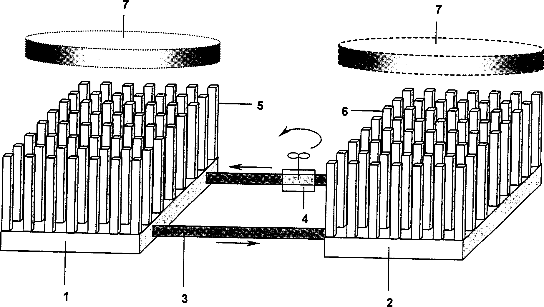
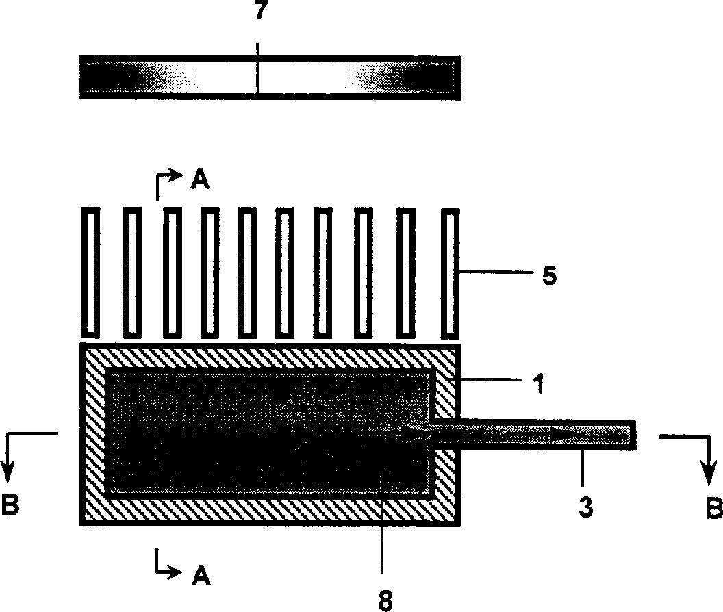
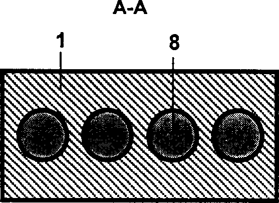
[0034] figure 1 It is a structural schematic diagram of the present invention, which is also an embodiment of the present invention; figure 2 It is a schematic diagram of the cross section (radiating ribs 5 and circulation channels) of the main radiator 1 of the present invention; Figure 2a to attach figure 2 Schematic diagram of the A-A section of ; attached Figure 2b to attach figure 2 The schematic diagram of the B-B cross-section; As can be seen from the figure, the chip heat dissipation device provided by the present invention as a flowing working medium with a low melting point metal or its alloy includes:

[0035] A main radiator 1 with a circulation channel inside, and a liquid low-melting point metal or its alloy flowing fluid is installed in the circulation channel, and the other surface of the main radiator 1 that is in contact with the su...


PUM

PropertyMeasurementUnit
melting pointaaaaaaaaaa

Abstract

The heat abstractor comprises a main radiator, an auxiliary radiator, a connecting pipe and a minipump. The main radiator possesses flow passages, where molten metal with low melting point or alloy flow working medium are contained. Cooling fins are setup at surface of the main radiator contacted to surface of the chip to be cooled. Cooling fins are also setup at surface of the auxiliary radiator possessing flow passages, where liquid metal with low melting point or alloying flow working medium are contained. The connecting pipe connects between the main and auxiliary radiators. The minipump is installed on the connecting pipe for driving liquid metal and working medium. The said working medium is metal gallium or its alloy, which are meltable near room temperature. The invention integrates fin cooling and convective cooling, providing advantages of small size, large cooling area, high heat transfer efficiency, close cyclic process without influence on environment.

Description

technical field [0001] The invention relates to a heat dissipation device for computer chips, in particular to a heat dissipation device for chip heat dissipation using a low-melting point metal or its alloy as a working medium. Background technique [0002] A notable feature of the development of the current microelectronics industry is the explosive growth of personal computers, workstations, and handheld computers. An important issue that follows is how to quickly and effectively dissipate the high heat generated in these systems. The difficulty of cooling a tiny system is: firstly, excessive cooling air velocity will cause large acoustic noise; secondly, the compactness of the device requires only a limited space for cooling fluid; thirdly, the installation of large surface heat sinks on the module should be avoided Shen. All of the above problems have raised the importance of developing high power density heat dissipation devices, and small size and high efficiency are...

Claims


Application Information

Patent Timeline
Patent Type & Authority Applications(China)
IPC IPC(8): G06F1/20H01L23/36
Inventor 刘静周一欣
Owner 北京中科高意引擎技术有限公司
Why Eureka
Try Eureka