Universal electrical wire harness quick detection device and method

A detection device, the technology of General Electric, is applied in the direction of measuring device, electrical connection test, measuring electricity, etc., which can solve the problems of difficult operation, high labor cost, low efficiency, etc., and achieve the effect of low cost and simple structure

Pending Publication Date: 2017-11-10
ZHENJIANG JINHAICHUANG TECH
View PDF10 Cites 2 Cited by
  • Summary
  • Abstract
  • Description
  • Claims
  • Application Information

AI Technical Summary

Problems solved by technology

[0004] The purpose of the present invention is to provide a quick detection device and method for general electrical wiring harness, to solve the technical problems of low efficiency, high labor cost and difficult operation of traditional detection methods existing in the prior art

Method used


Image

  • Universal electrical wire harness quick detection device and method
  • Universal electrical wire harness quick detection device and method
  • Universal electrical wire harness quick detection device and method

Examples


Embodiment 1

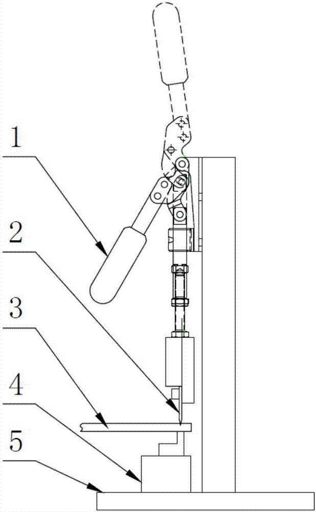
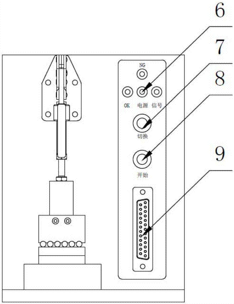
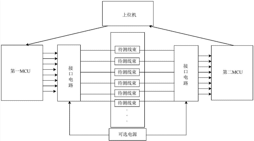
[0042] combine Figure 1 to Figure 2 As shown, the present embodiment provides a quick detection device for a general electric wire harness 3, which includes: a base 5, an insulating table 4, a cutter assembly, an insulating table 4, a wire harness interface 9 and a control system, and the insulating table 4 is arranged on The bottom of the base 5 is used to place the electric wiring harness 3 to be tested. The cutter assembly can be movably arranged above the insulating table 4 (when the cutter assembly is pressed down, the electrical wiring harness 3 to be tested is in a short-circuit state; when the cutter assembly is lifted, the electrical wiring harness 3 to be tested is in a short circuit state; In the disconnected state), the wire harness interface 9 is arranged on the side of the base 5 for accessing the electrical wire harness 3 to be tested; the control system includes: a host computer and signals connected to the host computer respectively The first MCU and the sec...

Embodiment 2

[0052] to combine Figure 1 to Figure 6 As shown, this embodiment also provides a method for a quick detection device for a general electric wire harness 3 according to Embodiment 1, which includes the following steps:

[0053] S1, laying the electrical wiring harness 3 to be tested on the insulating table 4;

[0054] S2. Connect one end of the electrical wire harness 3 to be tested into the wire harness interface 9;

[0055] S3. Control the cutter assembly to operate according to the detected category, wherein, when the cutter assembly is pressed down, the electrical wiring harness 3 to be tested is in a short circuit state; when the cutter assembly is lifted up, the electrical wiring harness 3 to be tested is in an open circuit state ;

[0056] S4. The control system performs detection processing according to the detection category, including:

[0057] S41. Send an instruction to the first MCU through the host computer. After receiving the instruction, the first MCU modif...


PUM


Abstract

The invention relates to the technical field of electrical wire harness detection, and especially relates to a universal electrical wire harness quick detection device and method. The device comprises a substrate, an insulating platform, a cutter assembly, the insulating platform, a wire harness interface, and a control system. The insulating platform is disposed at the bottom of the substrate, and the cutter assembly is movably disposed above the insulating platform. The wire harness interface is disposed at a side part of the substrate, and is used for connecting a to-be-detected electrical wire harness. The control system comprises an upper computer, a first MCU and a second MCU, wherein the first and second MCUs are in signal connection with the upper computer. The first and second MCUs are respectively connected with the to-be-detected electrical wire harness through an interface circuit. The device meets the detection demands of an electrical line, can detect the relations between the circuit break and short circuit and a line sequence at the same time, is low in cost, can be suitable for the detection of a complex wire harness, and is verified in the actual application.

Description

technical field [0001] The invention relates to the technical field of electric wire harness detection, in particular to a general electric wire harness quick detection device and method. Background technique [0002] Electrical wiring harness is an important part of current electrical equipment. Usually, various joints are made at both ends of the line by crimping, welding, etc., to complete the function of transmitting electrical signals and energy. At present, the traditional method of detecting open circuit, short circuit and line sequence relationship is: artificially use a multimeter to check one by one. However, this traditional detection method has low efficiency, high labor cost and difficult operation. There is no machine on the market that can detect open circuit, short circuit, and line sequence at the same time, let alone efficiently verify the correctness of the interface mode and line sequence. [0003] The information disclosed in this Background section is...

Claims


Application Information

Patent Timeline
Patent Type & Authority Applications(China)
IPC IPC(8): G01R31/02G01R31/04
CPCG01R31/67G01R31/50
Inventor 李婷
Owner ZHENJIANG JINHAICHUANG TECH
Why Eureka
Try Eureka