Array antenna

An array antenna and array technology, applied in the field of communication, can solve the problems of increased antenna volume, low gain, and great influence of antenna units, and achieve the effects of narrowing the beam width, improving the front-to-back ratio, and realizing miniaturization

Active Publication Date: 2017-11-17
GUANGDONG BROADRADIO COMM TECH
View PDF5 Cites 4 Cited by
  • Summary
  • Abstract
  • Description
  • Claims
  • Application Information

AI Technical Summary

Problems solved by technology

However, the distance between the two existing dual-polarized antenna arrays is set too close, and the influence between adjacent antenna elements is great, which has a great impact on the performance of the antenna, such as low gain, poor isolation, poor pattern out of shape
If the distance between adjacent antenna elements in two columns of dual-polarized antenna arrays is set far, the volume of the entire antenna will increase and its footprint will be large.

Method used


Image

  • Array antenna
  • Array antenna
  • Array antenna

Examples


Embodiment 1

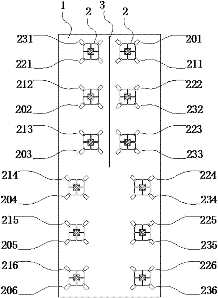
[0027] Such as figure 1 As shown, an array antenna includes: a metal reflector 1, a partition wall 3 and two low-frequency sub-arrays 2, and the two low-frequency sub-arrays 2 are arranged on the metal reflector 1 alternately, and the partition wall 3 is arranged along the metal reflector 1. The center line of the reflector 1 is set, and each low-frequency sub-array is composed of the first group of low-frequency radiation units, the second group of low-frequency radiation units and the third group of low-frequency radiation units, and the first group of low-frequency radiation units is arranged on one side of the partition wall 3 , the second group of low-frequency radiation units and the third group of low-frequency radiation units are arranged on the other side of the partition wall 3, the second group of low-frequency radiation units are arranged on a straight line close to and parallel to the center line of the metal reflector 1, the third group The low-frequency radiatio...

Embodiment 2

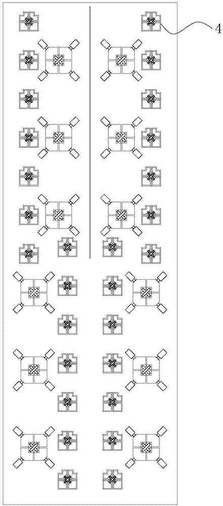
[0033] Such as figure 2 As shown, the low-frequency array arrangement in this example is the same as that in Embodiment 1. The high-frequency radiation unit 4 includes two oscillators that are orthogonal to each other, and a plurality of high-frequency radiation units 4 are arranged in four straight lines parallel to the centerline of the metal reflector. Above, four high-frequency arrays are formed, from left to right are the first high-frequency array, the second high-frequency array, the third high-frequency array, and the fourth high-frequency array. Each high-frequency array is composed of seven high-frequency radiation unit composition.

[0034] Among them, the first and fourth high-frequency arrays are located outside the straight line where the second and third radiation units of the two low-frequency arrays are located, and the second and third high-frequency arrays are located where the fourth, fifth and sixth radiation units of the two low-frequency arrays are loca...

Embodiment 3

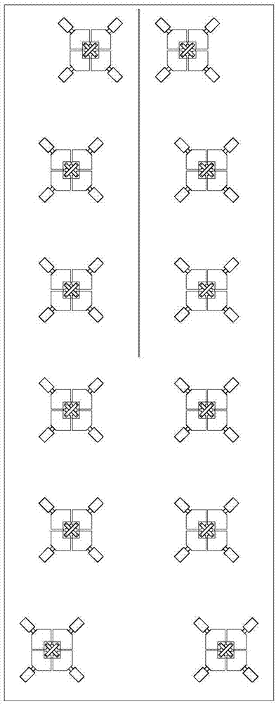
[0038] Such as image 3 As shown, the array antenna in this embodiment is basically the same as that in Embodiment 1, except that M=4 and N=1. The first radiating units of the two low-frequency sub-arrays are located between the straight lines where the second and third radiating units of the two low-frequency arrays are located.


PUM


Abstract

The invention relates to an array antenna, and the antenna comprises a metal reflection plate, an isolating wall and two low-frequency subarrays. The two low-frequency subarrays are intersected on the metal reflection plate, and the isolating wall is set along the central line of the metal reflection plate. Each low-frequency subarray consists of a first group of low-frequency radiation units, a second group of low-frequency radiation units, and a third groups of low-frequency radiation units. The first group of low-frequency radiation units are disposed at one side of the isolating wall, and the second group of low-frequency radiation units and the third group of low-frequency radiation units are disposed at the other side of the isolating wall. The second group of low-frequency radiation units are arranged on one line which is adjacent to and parallel to the central line of the metal reflection plate. The third group of low-frequency radiation units are arranged on the other line which is far from and is parallel to the central line of the metal reflection plate. According to the invention, the two antenna arrays are intersected with each other, thereby reducing the beam width of a horizontal plane, improving the front-to-back ratio, reducing the distance between the two antenna arrays, and achieving the miniaturization of the antenna.

Description

technical field [0001] The invention relates to the communication field, in particular to an array antenna. Background technique [0002] With the large-scale use of mobile intelligent terminals such as smartphones and tablet computers, as well as the astonishing growth of users of instant messaging software such as Facebook, WhatsApp, Twitter and WeChat, and the rapid development of wireless services such as mobile video, the data traffic of mobile communications Showing explosive growth, users put forward higher and higher requirements for the capacity of the communication system. On the other hand, as the difficulty of site construction increases, in order to reduce the cost of network construction, operators are required to achieve co-site and co-location. Therefore, multi-system, broadband and miniaturized base station antennas have become one of the current hot spots. [0003] Currently, a common technical means for improving system capacity is to use a MIMO (Multiple...

Claims


Application Information

Patent Timeline
Patent Type & Authority Applications(China)
IPC IPC(8): H01Q21/08H01Q1/52H01Q15/24H01Q5/20
CPCH01Q1/523H01Q5/20H01Q15/24H01Q21/08Y02D30/70
Inventor 张劭吴泽海苏振华吴壁群孙丹
Owner GUANGDONG BROADRADIO COMM TECH
Why Eureka
Try Eureka