Optical module

A technology of optical modules and light sources, which is applied in the field of optical modules, can solve the problems of low efficiency in positioning abnormal optical modules, and achieve the effect of improving efficiency

Active Publication Date: 2017-12-26
HISENSE BROADBAND MULTIMEDIA TECH
View PDF5 Cites 5 Cited by
  • Summary
  • Abstract
  • Description
  • Claims
  • Application Information

AI Technical Summary

Problems solved by technology

[0005] An embodiment of the present invention provides an optical module, which is used to solve the technical problem in the prior art that maintenance personnel have low efficiency in locating abnormal optical modules when the optical module is maintained due to the sealing of the optical module casing.

Method used


Image

  • Optical module
  • Optical module
  • Optical module

Examples


Embodiment Construction

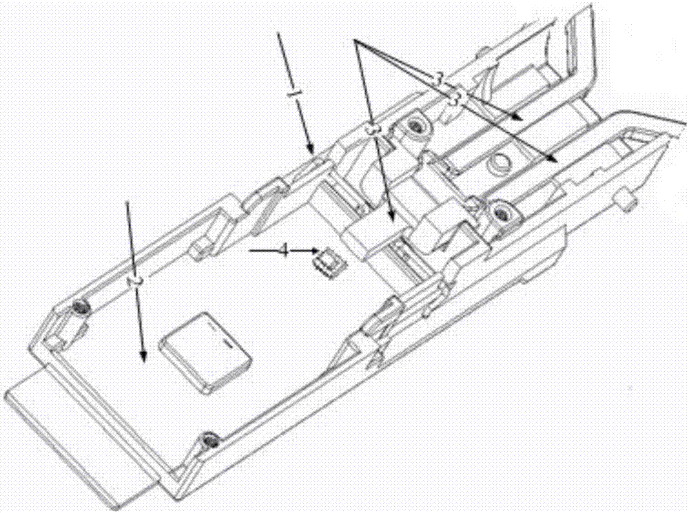
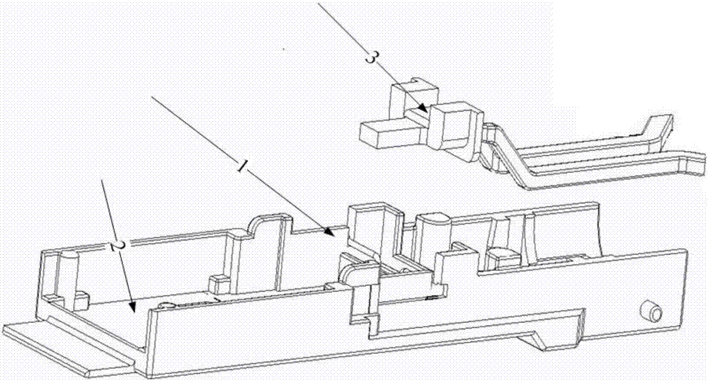
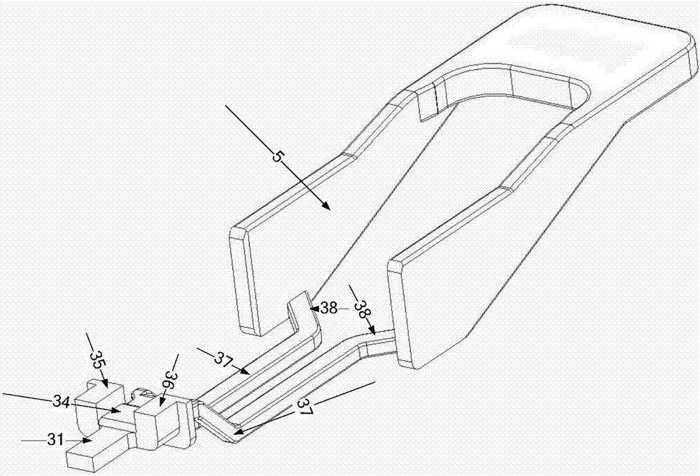
[0011] In order to solve the technical problem in the prior art that due to the sealing of the optical module housing, maintenance personnel have low efficiency in locating abnormal optical modules when performing optical module maintenance, an embodiment of the present invention provides an optical module, which includes Light guide structure, housing, circuit board, a part of the light guide structure is placed in the housing, and the other part of the light guide structure protrudes from the housing; a light source is arranged on the circuit board, and the light guide structure is used to transmit the light emitted by the light source conducted to the outside of the enclosure. The light guide structure in the optical module can transmit the light emitted from the inside of the optical module to the outside of the optical module. The optical module of the present invention can transmit and present some conditions inside the optical module with the optical signal as the propag...


PUM


Abstract

The invention discloses an optical module which is used for solving the technical problem of low detection efficiency of an abnormal optical module in the prior art. The optical module comprises a housing, a circuit board and a light guiding structure; one part of structure of the light guiding structure is arranged in the housing, and the other part of structure of the light guiding structure extends out of the housing; and a light source is arranged on the circuit board, and the light guiding structure is used for conducting light emitted by the light source to the outside of the housing. The light guiding structure in the optical module can conduct the light emitted from the inside of the optical module to the outside of the optical module; the optical module disclosed by the invention can achieve an effect of conducting and showing conditions inside the optical module outside the optical module by using the optical signal as a propagation medium, so that the conditions inside the optical module can be directly known from the outside of the housing of the optical module and various application scenes of the optical module are further expanded.

Description

technical field [0001] Embodiments of the present invention relate to the field of communication technologies, and in particular, to an optical module. Background technique [0002] With the rapid development of Internet business, large-scale data centers and cloud devices have been newly built all over the world. Each device needs to apply a few or as many as dozens of optical modules. In the early stage of equipment and system It will consume huge manpower and material resources when building and debugging. Whether the installed equipment and optical modules are working normally cannot be seen from the actual optical modules. It is necessary to use professional monitoring equipment and monitoring programs to read the working status information of each optical module, and this monitoring equipment generally Set it in the optical module monitoring area far from the optical module working area. [0003] When performing abnormal detection of optical modules, it is usually ne...

Claims


Application Information

Patent Timeline
IPC IPC(8): H04B10/40H04B10/07
CPCH04B10/07H04B10/40
Inventor 杨思更刘寅龙黄永亮贲仕建夏京盛何鹏徐海强薄生伟李腾跃
Owner HISENSE BROADBAND MULTIMEDIA TECH
Why Eureka
Try Eureka