Wireless signal transmit-receive apparatus and wireless signal transmit-receive chain

A wireless signal and transceiver technology, applied in the field of communication, can solve problems such as high system complexity, invisible, high weather conditions, and reduced wireless communication quality

Active Publication Date: 2017-12-29
BEIJING PHOENIX HUITONG TECH CO LTD +1
View PDF5 Cites 1 Cited by
  • Summary
  • Abstract
  • Description
  • Claims
  • Application Information

AI Technical Summary

Problems solved by technology

Long-distance wireless communication due to climate change, such as rain, snow, fog and other harsh weather phenomena will not only reduce the quality of wireless communication, but even interrupt communication, so that wireless communication will lose the important support means of high-speed rail informatization and intelligence will directly lead to the failure of high-speed rail informatization and intelligence
[0006] Similarly, although wireless optical communication is not affected by the Doppler effect, it has too high requirements on meteorological conditions and the high complexity of the system. At present, it is not possible to see the possibility of this technology being applied to high-speed rail communication, while satellite communication In addition to the limitation of communication bandwidth, weak satellite signals and too many railway tunnels in high-latitude areas are also the main reasons that limit the application of satellite communication in high-speed rail vehicle-ground communication

Method used


Image

  • Wireless signal transmit-receive apparatus and wireless signal transmit-receive chain
  • Wireless signal transmit-receive apparatus and wireless signal transmit-receive chain
  • Wireless signal transmit-receive apparatus and wireless signal transmit-receive chain

Examples


Embodiment Construction

[0051] The technical solutions of the present invention will be described in further detail below with reference to the accompanying drawings and embodiments.

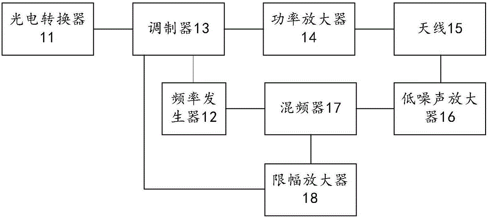
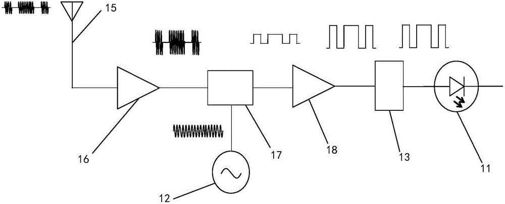
[0052] figure 1 A schematic structural diagram of a wireless signal transceiving device provided for an embodiment of the present invention, such as figure 1 As shown, the wireless signal transceiving device includes an antenna 15 , a low noise amplifier 16 , a mixer 17 , a frequency generator 12 , a limiting amplifier 18 , a modulator 13 and a photoelectric converter 11 .

[0053] The antenna 15 receives the pulse signal sent by the external wireless communication device, and sends it to the low noise amplifier 16 . The low-noise amplifier 16 performs low-noise amplification processing on the pulse signal received by the antenna 15 , generates a processed pulse signal, and sends it to the mixer 17 . The frequency generator 12 generates a frequency signal and sends it to the mixer 17 . The mixer 17 processes the frequ...


PUM


Abstract

The invention relates to a wireless signal transmit-receive apparatus, comprising an antenna, a low noise amplifier, a mixer, a frequency generator, an amplitude limit amplifier, a modulator and a photoelectric converter. The antenna is used for receiving a pulse signal. The low noise amplifier is used for conducting low noise amplification on the pulse signal received by the antenna, and generating processing pulse signal and sending to the mixer. The frequency generator is used for generating a frequency signal and sending it to the mixer. The mixer processes the frequency signal into communication electric signal based on the processing pulse signal. The amplitude limit amplifier is used for conducting amplitude limit amplification on the communication electric signal, and generating amplification electric signal. The modulator is used for conducting protocol transition on the amplification electric signal and generating electric signal. The photoelectric converter is used for converting the electric signal to the optical signal, and sending the optical signal to an optical receiver. The invention is advantageous in that millimeter wave communication technology and optical communication technology are combined, and the special-purpose communication protocol is adopted to achieve vehicle-earth large-capacity and high-reliability data communication of trains under condition of high-speed movement.

Description

technical field [0001] The invention relates to the field of communication technology, in particular to a wireless signal transceiving device and a wireless signal transceiving chain. Background technique [0002] So far, the purpose of all mobile communication systems is to solve personal communication. Therefore, from the first generation mobile communication system to the current 5G mobile communication system, all the development of mobile communication technology is to improve the quality of personal communication. Therefore, it is unrealistic to try to solve the vehicle-to-ground communication of high-speed trains under wide-area conditions based on the existing mobile communication technology or existing infrastructure. In fact, GSM-R, which evolved from GSM technology, is increasingly unable to meet the increasingly urgent information and intelligent vehicle-to-ground communication needs of high-speed railway transportation, and there is no effective progress in this...

Claims


Application Information

Patent Timeline
Patent Type & Authority Applications(China)
IPC IPC(8): H04B1/40H04B1/3822H04W4/00H04B5/00
CPCH04B1/3822H04B1/40H04B5/0025H04W4/80
Inventor 黄永江
Owner BEIJING PHOENIX HUITONG TECH CO LTD
Why Eureka
Try Eureka