
An intelligent fresh-keeping equipment monitoring device
A monitoring device and equipment technology, applied in the direction of measuring devices, mechanical equipment, instruments, etc., can solve the problems of inconvenient air humidity monitoring, inconvenient humidity sensor adjustment, etc., and achieve the effects of high practical performance, high degree of automation, and convenient operation.
- Summary
- Abstract
- Description
- Claims
- Application Information
AI Technical Summary
Problems solved by technology
Method used
Image

Examples
Embodiment
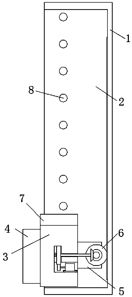
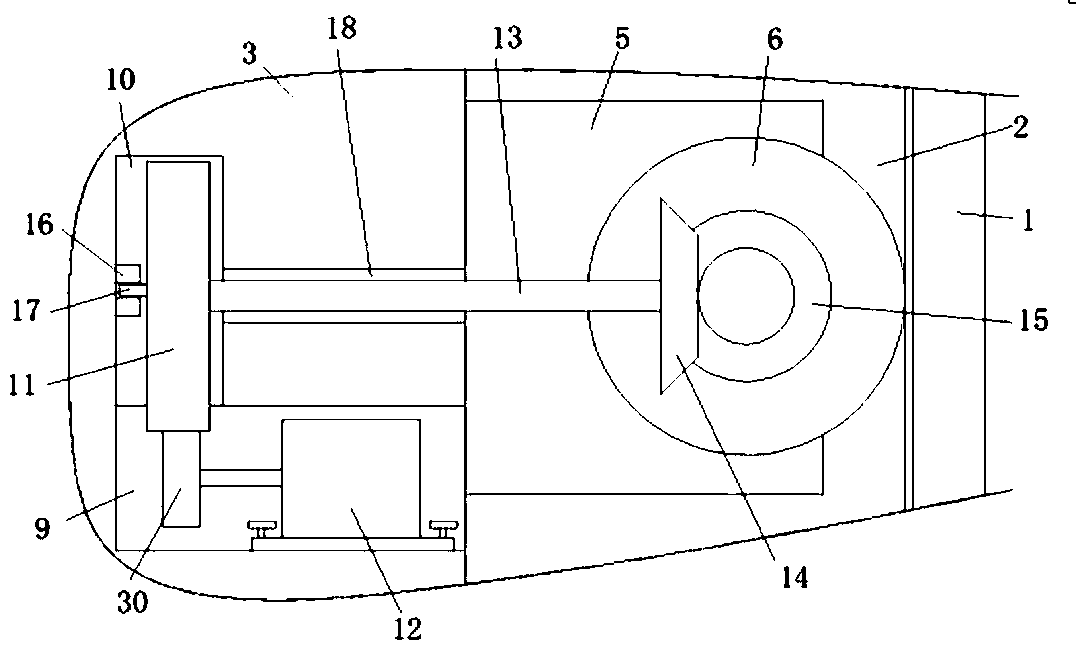
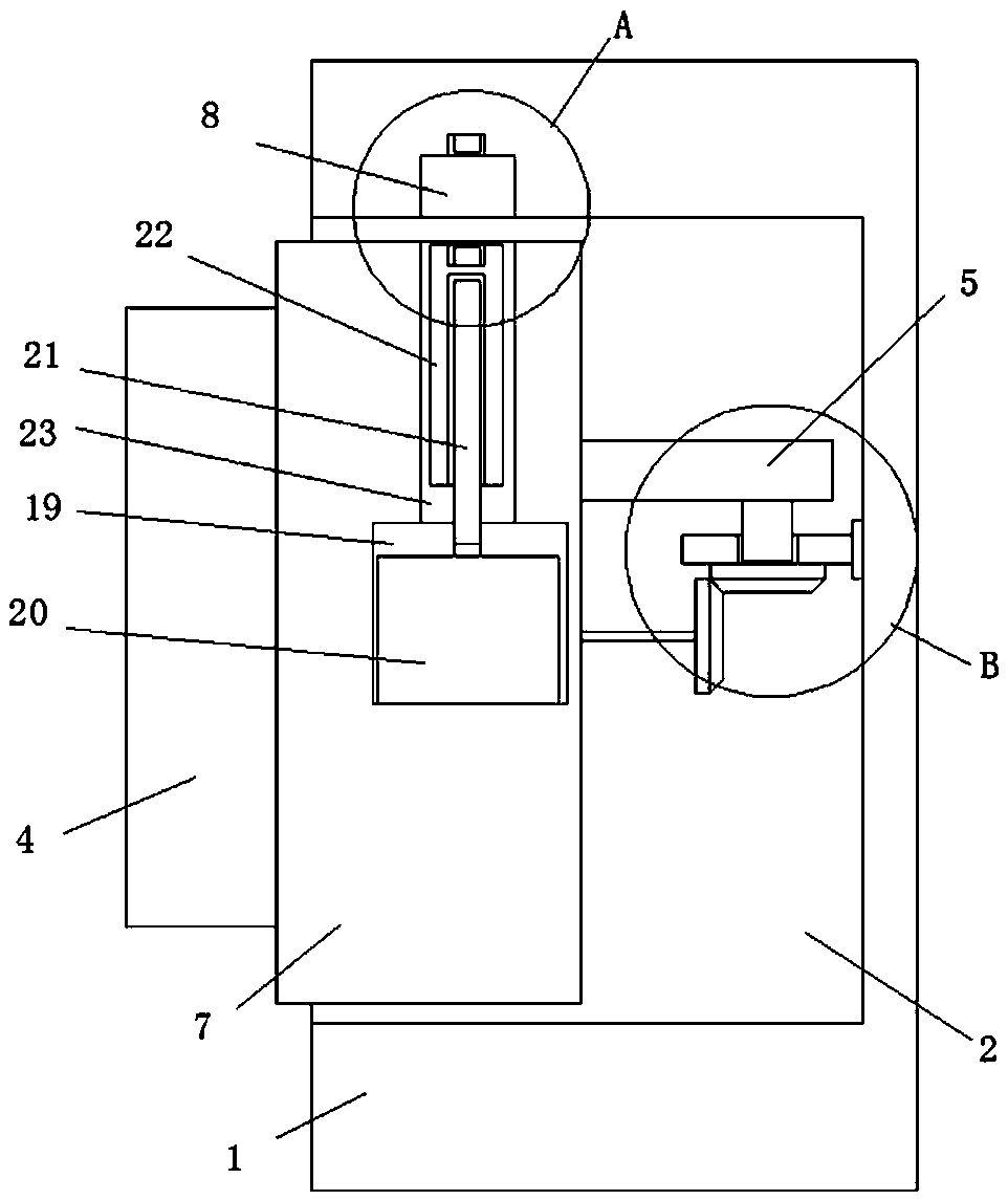
[0022] refer to Figure 1-5 , an intelligent fresh-keeping equipment monitoring device is proposed in this embodiment, including a monitoring rod 1, a chute 2 is provided on one side of the monitoring rod 1, an adjusting block 3 is slidably installed in the chute 2, and one side of the adjusting block 3 Extending to the outside of the monitoring rod 1 and fixedly installed with a humidity sensor 4, the other side of the adjustment block 3 is welded with a connecting plate 5, the connecting plate 5 is rotatably mounted with a slave gear 6, and the inner wall of the chute 2 is provided with teeth The gear 6 is meshed with the rack, and the auxiliary bevel gear 15 is welded on the side away from the connecting plate 5 from the gear 6. The side of the adjustment block 3 away from the humidity sensor 4 is provided with a mounting groove 9, and the top of the mounting groove 9 A rotating groove 10 is opened on the inner wall, and a main gear 11 is installed in the rotating groove 10...
PUM
 Abstract
Description
Claims
Application Information