Supercharge Your Innovation With Domain-Expert AI Agents!

Improved type power supply plug device

An improved plug-in technology for power supply, which is applied to the parts of the connection device, coupling device, circuit, etc., can solve the problems of young children's casualties, electric shock accidents, and unstable conditions, etc., and achieves convenient use and high electricity safety. , resulting in a simple effect

Inactive Publication Date: 2018-02-09
泉州市莱特灯具有限公司
View PDF1 Cites 0 Cited by
  • Summary
  • Abstract
  • Description
  • Claims
  • Application Information

AI Technical Summary

Problems solved by technology

[0002] There are many news reports about electric shock accidents every year, and a large proportion of them are children's electric shock accidents. Due to the curiosity of young children, they will insert metal rods into the slots, and the metal rods will be in contact with the input conductive sheet , because the input conductive sheet is directly connected to the mains, it will cause electric shock accidents, and in severe cases, it will cause casualties to young children. , just rely on the elastic clamping of the input conductive sheet to keep the household appliances in the energized state, but this state is not stable enough. When someone accidentally touches the power connector or the wire, it will cause the power connector to loosen or fall. Therefore, it will cause unexpected power failure of household appliances, which will easily affect household appliances.

Method used


Image

  • Improved type power supply plug device
  • Improved type power supply plug device
  • Improved type power supply plug device

Examples


Embodiment Construction

[0027] All features disclosed in this specification, or steps in all methods or processes disclosed, may be combined in any manner, except for mutually exclusive features and / or steps.

[0028] Any feature disclosed in this specification (including any appended claims, abstract and drawings), unless expressly stated otherwise, may be replaced by alternative features which are equivalent or serve a similar purpose. That is, unless expressly stated otherwise, each feature is one example only of a series of equivalent or similar features.

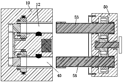
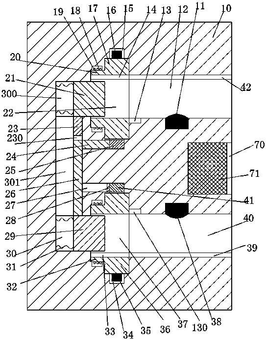
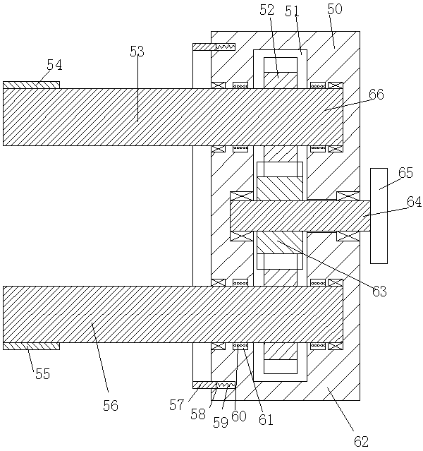
[0029] Such as Figure 1 to Figure 8As shown, an improved power supply plug-in device of the device of the present invention includes a power base 10 fixedly installed in the wall and a plug connector matched with the power base 10, and the power base 10 is symmetrically arranged up and down. The upper slot 12 and the lower slot 40 with the opening to the right, the upper conductive block 11 and the lower conductive block 38 are respectively ...


PUM


Abstract

The invention discloses an improved type power supply plug device. The improved type power supply plug device comprises a power supply base fixedly mounted in a wall body, and a plug part; an upper slot and a lower slot with rightward openings are symmetrically formed in the power supply base up and down; an upper conductive block and a lower conductive block are mounted in the inner side end walls of the upper slot and the lower slot respectively; an upper rotation block and a lower rotation block are rotationally mounted at the left ends of the upper slot and the lower slot respectively; anupper rotation arm and a lower rotation arm are fixedly arranged at the left ends of the upper rotation block and the lower rotation block respectively; a first annular groove and a second annular groove are formed in the peripheries of the upper rotation block and the lower rotation block respectively; an upper conductive head and a lower conductive head are fixedly arranged on the outer side endwalls of the first annular groove and the second annular groove respectively; the upper conductive head and the lower conductive head are electrically connected with the upper conductive block and the lower conductive block respectively; and an upper power supply head and a lower power supply plug which are connected with the mains supply and extend into the first annular groove and the second annular groove respectively are mounted in the positions, close to the outer end, of the upper rotation block and the lower rotation block respectively.

Description

technical field [0001] The invention relates to the field of electricity utilization for household appliances, in particular to an improved power supply plug-in device. Background technique [0002] There are many news reports about electric shock accidents every year, and a large proportion of them are children's electric shock accidents. Due to the curiosity of young children, they will insert metal rods into the slots, and the metal rods will be in contact with the input conductive sheet , because the input conductive sheet is directly connected to the mains, it will cause electric shock accidents, and in serious cases, it will cause casualties to young children. , relying solely on the elastic clamping of the input conductive sheet to keep the household appliances powered on, but this state is not stable enough. When someone accidentally touches the power connector or the wire, it will cause the power connector to loosen or fall. Therefore, an accidental power failure...

Claims


Application Information

Patent Timeline
Patent Type & Authority Applications(China)
IPC IPC(8): H01R13/639H01R13/70H01R13/447
CPCH01R13/639H01R13/447H01R13/701
Inventor 孙旭东
Owner 泉州市莱特灯具有限公司
Features
  • R&D
  • Intellectual Property
  • Life Sciences
  • Materials
  • Tech Scout
  • Unparalleled Data Quality
  • Higher Quality Content
  • 60% Fewer Hallucinations
Learn More