Supercharge Your Innovation With Domain-Expert AI Agents!

Novel dust remover device

A dust collector, a new type of technology, applied in the direction of coupling devices, parts of connecting devices, electrical components, etc., can solve problems such as electric shock, casualties, power failure of dust collectors, etc., and achieve high electricity safety, simple results, and easy to use convenient effect

Inactive Publication Date: 2018-02-06
ANXI BAIJIAYI HOUSEHOLD ARTICLES CO LTD
View PDF1 Cites 0 Cited by
  • Summary
  • Abstract
  • Description
  • Claims
  • Application Information

AI Technical Summary

Problems solved by technology

[0002] Industrial dust collectors are widely used in industrial production. However, the power of industrial dust collectors is relatively large. In some factories, power supply cabinets are specially equipped for plugging and power supply of dust collectors. There are electric connection sockets in the power supply cabinets. However, these electric connection sockets are set The mode is single, and the internal conductive sheet is set relatively outside. This conductive sheet is easily touched by the metal sheet or metal rod. Therefore, when people who lack safety awareness insert the metal rod into the electrical socket, it is easy to get an electric shock. In addition, the traditional dust collector is extremely unstable when the power supply is connected. If you accidentally kick the electrical connector or trip over the wire, it will cause the electrical connector to fall off and cause the dust collector to accidentally power outage

Method used


Image

  • Novel dust remover device
  • Novel dust remover device
  • Novel dust remover device

Examples


Embodiment Construction

[0027] All features disclosed in this specification, or steps in all methods or processes disclosed, may be combined in any manner, except for mutually exclusive features and / or steps.

[0028] Any feature disclosed in this specification (including any appended claims, abstract and drawings), unless expressly stated otherwise, may be replaced by alternative features which are equivalent or serve a similar purpose. That is, unless expressly stated otherwise, each feature is one example only of a series of equivalent or similar features.

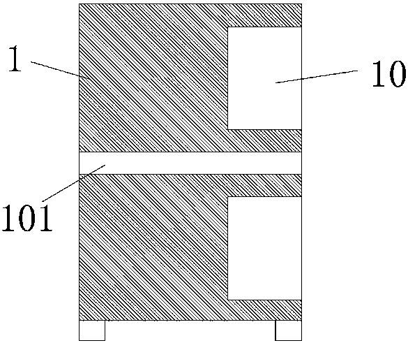
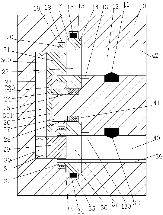
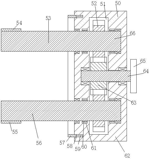
[0029] Such as Figure 1 to Figure 8As shown, a new dust collector device of the device of the present invention includes a power supply cabinet 1 and an electrical connector connected to the dust collector. Seat 10, the upper and lower insertion chambers 12 and lower insertion chambers 40 with the openings facing right are respectively arranged in the upper and lower sides of the electrical connection seat 10, and upper power transmission bl...


PUM


Abstract

The invention provides a novel dust remover device, which comprises a power supply cabinet and a power head connected with a dust remover. At least two sets of power connection bases are arranged up and down in the power supply cabinet through partition plates. The power connection bases are internally provided with an upper insertion cavity and a lower insertion cavity, wherein the upper insertion cavity and the lower insertion cavity are arranged correspondingly up and down, and are provided with rightward opening ends. An upper power transmission block and a lower power transmission block are respectively arranged in the sidewalls of the inner sides of the upper insertion cavity and the lower insertion cavity. An upper rotary table and a lower rotary table are respectively arranged at the left ends of the upper insertion cavity and the lower insertion cavity in the annularly rotatable manner. The left end of the upper rotary table and the left and of the lower rotary table are respectively and fixedly provided with an upper rotary plate and a lower rotary plate. The outer end surfaces of the upper rotary table and the lower rotary table are respectively provided with a first annular cavity and a second annular cavity. An upper power transmission piece and a lower power transmission piece are fixedly arranged on the outer side end walls of the first annular cavity and the outer side end wall of the second annular cavity respectively. The upper power transmission piece and the lower power transmission piece are respectively and electrically connected with the upper power transmission block and the lower power transmission block.

Description

technical field [0001] The invention relates to the field of dust collectors, in particular to a novel dust collector device. Background technique [0002] Industrial dust collectors are widely used in industrial production. However, industrial dust collectors have relatively high power. In some factories, power supply cabinets are specially equipped for plugging and power supply of dust collectors. There are electric connection blocks in the power supply cabinets. However, these electric connection blocks are set The mode is single, and the internal conductive sheet is set relatively outside. This conductive sheet is easily touched by the metal sheet or metal rod. Therefore, when people who lack safety awareness insert the metal rod into the electrical socket, it is easy to get an electric shock. In addition, the traditional dust collector is extremely unstable when it is connected to the power supply. If you accidentally kick the electric connector or trip over the wire,...

Claims


Application Information

Patent Timeline
IPC IPC(8): H01R13/70H01R13/639H01R13/447
CPCH01R13/701H01R13/447H01R13/639
Inventor 范盛林
Owner ANXI BAIJIAYI HOUSEHOLD ARTICLES CO LTD
Features
  • R&D
  • Intellectual Property
  • Life Sciences
  • Materials
  • Tech Scout
  • Unparalleled Data Quality
  • Higher Quality Content
  • 60% Fewer Hallucinations
Learn More