Supercharge Your Innovation With Domain-Expert AI Agents!

Electric control valves for coolant compressors

A control valve, electrical control technology, applied in refrigerators, refrigeration components, mechanical equipment, etc., can solve the problems of material fatigue, aging, and inability to ensure that the bellows filled with gas mixtures are kept tight, etc., to achieve cost-effective results

Active Publication Date: 2019-02-15
TE CONNECTIVITY GERMANY GMBH
View PDF5 Cites 0 Cited by
  • Summary
  • Abstract
  • Description
  • Claims
  • Application Information

AI Technical Summary

Problems solved by technology

[0021] However, this type of bellows is a mechanically operating part, which is sluggish due to construction and also undergoes an aging process
Thus, for example, the frequent unfolding of the bellows in the shape of an accordion and subsequent folding leads to fatigue of the material therein
Furthermore, in some cases it cannot be ensured that a bellows filled with a gas mixture will remain tight during its service life

Method used


Image

  • Electric control valves for coolant compressors

Examples


Embodiment Construction

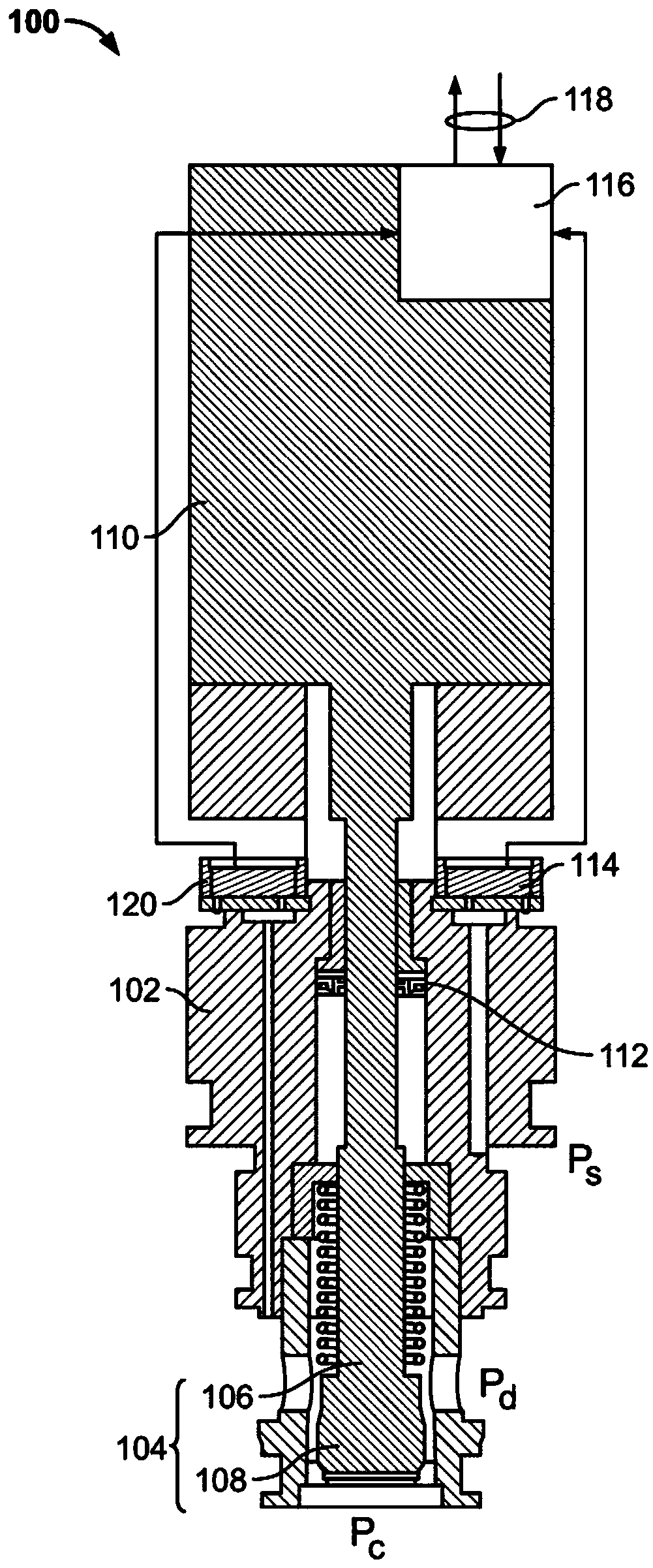
[0035] After this, refer to figure 1 , first the general inventive principle of the electric control valve 100, in particular for a coolant compressor, for controlling the coolant from the high pressure area into the crankcase-chamber-pressure area will be described in more detail flow.

[0036] figure 1 A control valve according to the present invention for a coolant compressor of a first embodiment is shown; embodiments of individual components of the control valve and improvements of the control valve are described in more detail in connection with the description. A control valve 100 controls the flow of coolant from the high pressure area of ​​a coolant compressor (not shown) into the crankcase-chamber-pressure area. For this purpose, the control valve 100 comprises a valve housing 102 with a connector Pd for connection to the high-pressure area of ​​the coolant compressor, with a connector Pd for connection to the crankcase-chamber-pressure area of ​​the coolant compre...


PUM


Abstract

This invention relates to electrically controlled valves for controlling coolant flow. The control valve consists of: a valve housing with connectors for the suction-pressure area, the high-pressure area and the crankcase-chamber-pressure area; a valve body arranged to be displaceable between two positions, depending on position, the valve body interconnects or separates the high-pressure area and the crankcase-chamber-pressure area; the electric actuation driver, which displaces the valve body; the device for determining the position of the valve body; the first pressure sensor, which determines the suction- The value of the suction pressure in the pressure area; the electric control means, as a function of the determined value of the suction pressure, which controls the coolant flow by displacing the valve body with an electrically actuated drive such that if the determined suction pressure drops to a predetermined Determined below the critical value, the valve body connects the high-pressure area to the crankcase-chamber-pressure area, and an electrical interface via which the value determined by the first pressure sensor can be read and via which the control valve can be connected to the power supply.

Description

technical field [0001] The present invention relates to an electrically controlled valve for use in coolant compressors, in particular for use in coolant compressors for motor vehicles. An electrically controlled valve controls the flow of coolant from the high pressure area of ​​the coolant compressor into the crankcase-chamber-pressure area. Background technique [0002] Both the construction and the mode of operation of coolant compressors are known to the person skilled in the art, for example from DE 10 2011 117 354 A1. [0003] In the crankcase of the coolant compressor, a plurality of pistons are arranged to pump the coolant into the high pressure chamber. The movement of the pistons is guided by a rotating swash plate, as will become clear from the following description. [0004] If the swashplate, which is rotated eg by a belt drive, has a non-zero inclination angle, this results in an axial stroke movement of the piston during rotation of the swashplate about its...

Claims


Application Information

Patent Timeline
Patent Type & Authority Patents(China)
IPC IPC(8): F04B27/18
CPCF04B27/1804F04B2027/1827F04B2027/1813F04B2027/1859F04B2027/1854F04B2027/1831F25B49/022F25B2700/1933F04B2027/1818
Inventor D.多姆克
Owner TE CONNECTIVITY GERMANY GMBH
Features
  • R&D
  • Intellectual Property
  • Life Sciences
  • Materials
  • Tech Scout
  • Unparalleled Data Quality
  • Higher Quality Content
  • 60% Fewer Hallucinations
Learn More