Core rod testing remote alarming system and method based on image identification

An image recognition and remote alarm technology, applied in the field of the Internet of Things, can solve problems such as unfavorable test automation, inability to diagnose and schedule equipment status, and no historical alarm information records of test equipment, so as to reduce the workload of human eye monitoring and reduce image Identify the effects of processing data volumes

Active Publication Date: 2018-03-09
SHANTOU HIGH TECH ZONE AOXING OPTICAL COMM EQUIP
View PDF12 Cites 7 Cited by
  • Summary
  • Abstract
  • Description
  • Claims
  • Application Information

AI Technical Summary

Problems solved by technology

With the disappearance of the demographic dividend and the gradual increase in labor costs, this approach no longer has advantages and is not conducive to the realization of test automation
Moreover, there is no historical alarm information record of the test equipment, and it is impossible to accurately diagnose and schedule the equipment status

Method used


Image

  • Core rod testing remote alarming system and method based on image identification
  • Core rod testing remote alarming system and method based on image identification
  • Core rod testing remote alarming system and method based on image identification

Examples


Embodiment 1

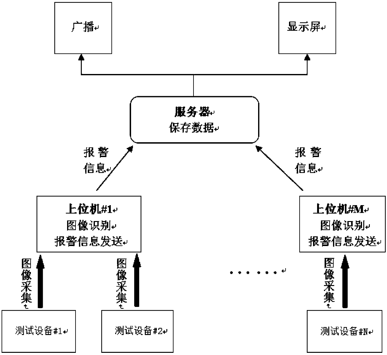
[0040] Such as figure 1 As shown, a kind of image recognition-based mandrel test remote alarm system according to the present invention includes:

[0041] Mandrel testing equipment

[0042] A DOS environment mandrel testing equipment PK2600.

[0043] image capture device

[0044] A PCIE image acquisition card with VGA interface.

[0045] PC

[0046] A computer with win7 system installed with image processing program.

[0047] Image acquisition module:

[0048] According to the development kit provided by the image acquisition equipment supplier, write the image acquisition module program. Since the system does not require high real-time performance, it can be set to acquire the device screen image every 200ms.

[0049] Image recognition module:

[0050] Store the reference pictures in advance, use the PCIE image acquisition card to collect all possible screen pictures of the test equipment PK2600 and save them in bmp format.

[0051] After analysis and comparison, the ...

Embodiment 2

[0061] Remote alarm system for mandrel testing based on image recognition, including:

[0062] 1. Mandrel testing equipment

[0063] 8 sets of DOS environment mandrel testing equipment PK2600, numbered #1, #2, #3, #4, #5, #6, #7, #8.

[0064] 2. Image acquisition equipment

[0065] 4 PCIE image acquisition cards with dual VGA interfaces. Since in the mandrel testing workshop, every two mandrel testing equipments are placed very close to each other, from the perspective of saving the upper computer, the two mandrel testing equipments share one image acquisition card.

[0066] 3. The upper computer has 4 computers with win7 system installed with image processing programs.

[0067] The basic principle of the image processing program is the same as that of the implementation example 1.

[0068] 4. Server

[0069] Install the oracle or sqlserver database to store the alarm information sent by the host computer, including: device number, alarm type, and time. In this embodimen...


PUM


Abstract

The invention discloses a core rod testing remote alarming system and method based on image identification. The system includes core rod testing equipment, an upper computer, a server and alarming equipment, wherein the core rod testing equipment is connected with image collecting equipment, the upper computer includes an image collecting module, an image identification module and an alarming information uploading module, and the image collecting module collects screen images of the core rod testing equipment according to a preset collection time interval; the image identification module carries out image comparison on the collected real-time images with prestored reference images to achieve identification of the images of an alarming screen; the alarming information uploading module is used for sending the identified alarming information to the server; the server is used for storing alarming information sent by the upper computer; the alarming equipment is used for reminding people about the alarming information. By means of the image collecting equipment, the screen images of the core rod testing equipment can be caught in real time, the alarming information is identified in theupper computer and stored into the server, an operator is reminded by the alarming equipment to dispose problems in time, and remote alarming of a core rod test is achieved.

Description

technical field [0001] The invention relates to the field of the Internet of Things, in particular, the invention relates to a remote alarm system and method for mandrel testing based on image recognition. Background technique [0002] Optical fiber core rod is an important basic material for making optical fiber. It basically determines the characteristics and quality of the finished optical fiber. With the upgrading of my country's optical fiber industry, the test of the core rod has become an increasingly important link. Proceed to the next step. [0003] The mandrel test has been basically automated, and due to the long test time, about one to two hours, this process is often unattended. If the test is suspended after the test is completed, or the equipment alarms during the test, and the operator is not in front of the equipment, the alarm information and equipment status cannot be obtained in time, and the test process cannot be intervened immediately, which will lead ...

Claims


Application Information

Patent Timeline
Patent Type & Authority Applications(China)
IPC IPC(8): G06T7/00G01N21/84G08B21/00H04N5/232
CPCG06T7/001G08B21/00G01N21/84H04N23/80
Inventor 邵慧何幼林周冠宇王长兴黄子恒
Owner SHANTOU HIGH TECH ZONE AOXING OPTICAL COMM EQUIP
Why Eureka
Try Eureka