Movable supporting framework plate supporting structure for roadway

A supporting structure and supporting bone technology, which is applied in the direction of mine roof support, mining equipment, mining equipment, etc., can solve the problems of difficult protection, inability to prevent deformation of surrounding rock, and difficulty in repeated use, so as to achieve good protection and slow down the acceleration of gravity , the effect of reducing the impact force

Active Publication Date: 2018-10-19
邓立杰
View PDF6 Cites 5 Cited by
  • Summary
  • Abstract
  • Description
  • Claims
  • Application Information

AI Technical Summary

Problems solved by technology

Although the above-mentioned support methods can basically effectively prevent and protect the "roof caving", they also have the disadvantages of cumbersome procedures, long construction period, high labor intensity, high cost, and cannot or are difficult to reuse
In particular, the widely used I-steel trapezoidal rigid bracket support, because the rigid bracket cannot adapt to the deformation and movement of the surrounding rock, and is unable to prevent the deformation of the surrounding rock, it is difficult to avoid deformation and damage caused by overload support
Therefore, for the underground mine rigid support support, it can not form long-term support for the roadway, and it is difficult to form effective protection when the "roof collapse" is caused by the support gap of the rigid support support. Auxiliary measures such as slurry are used for protection, so that the underground must be constructed gradually on site to form a complete support structure, which makes the construction period long and labor-intensive, and the supports and anchor nets cannot be reused, resulting in high overall costs.

Method used


Image

  • Movable supporting framework plate supporting structure for roadway
  • Movable supporting framework plate supporting structure for roadway
  • Movable supporting framework plate supporting structure for roadway

Examples


Embodiment Construction

[0021] The present invention will be further described below with reference to the accompanying drawings and embodiments, but the present invention is not restricted in any way. Any changes or improvements made based on the teachings of the present invention shall fall within the protection scope of the present invention.

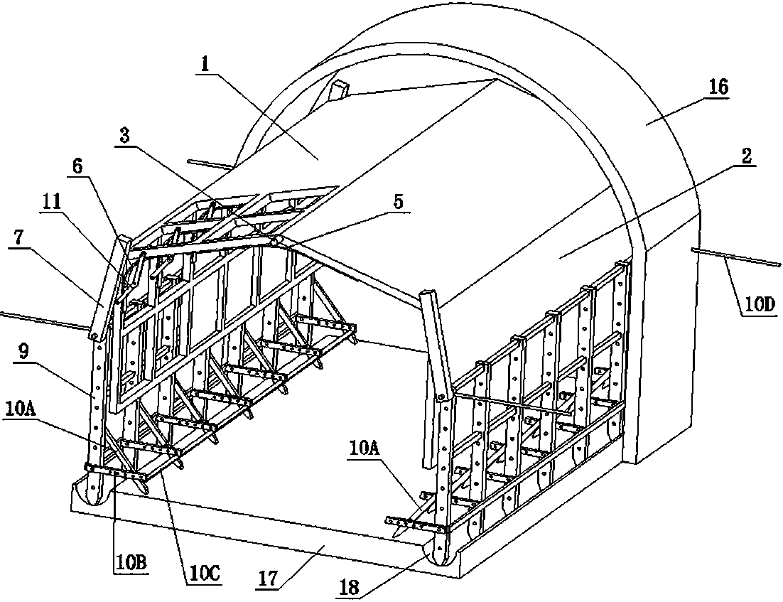
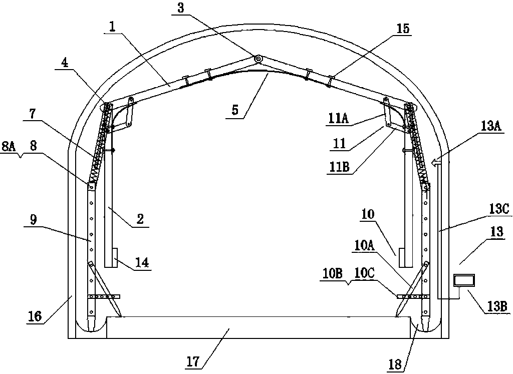
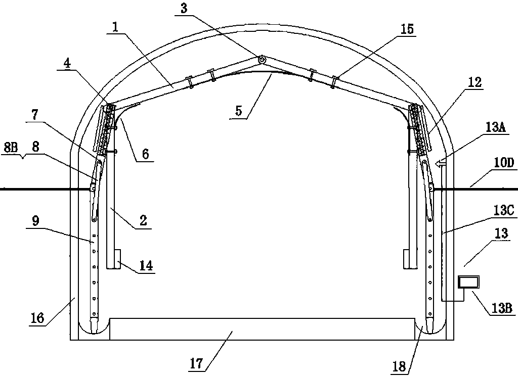
[0022] Such as Figure 1 to 5 As shown, the present invention includes an upper baffle 1, a side baffle 2, a top rotating shaft 3, a side rotating shaft 4, an elastic piece 5, a limiting elastic piece 6, an elastic compression rod 7, a torsion support mechanism 8, a pillar 9, and a pillar support mechanism 10. One end of the upper baffle 1 is hinged with the top shaft 3 and the other end is fixedly connected or hinged with the side shaft 4, the upper end of the side baffle 2 is fixedly connected or hinged with the side shaft 4, and the top shaft 3 extends along the direction of the roadway The upper baffle 1 arranged and hinged on both sides forms an inverted ...


PUM


Abstract

The invention discloses a movable supporting framework plate supporting structure for a roadway. According to the movable supporting framework plate supporting structure, one ends of upper baffles arehinged to top rotating shafts, the other ends of the upper baffles are fixedly connected to or hinged to side rotating shafts, the upper ends of side baffles are fixedly connected to or hinged to theside rotating shafts, the top rotating shafts are arranged in the extending direction of the roadway, the upper baffles hinged to the two sides of the top rotating shafts are inverted-U-shaped or inverted-V-shaped, the two sides of an elastic sheet are fixedly connected to the lower surfaces of the upper baffles on the two sides separately, limiting elastic sheets are C-shaped and are arranged onthe lower surfaces of the upper baffles and the inner side surfaces of the side baffles, one sides of the limiting elastic sheets are fixedly connected to the upper baffles or the side baffles, the two ends of the side rotating shafts are hinged to the compression ends of elastic compression rods on the two sides separately, the fixed ends of the elastic compression rods are hinged to supportingcolumns, the two ends of torsion supporting mechanisms are connected to the fixed ends of the elastic compression rods and the supporting columns, the other ends of the supporting columns are arrangedon a roadway base plate, and one ends of supporting column supporting mechanisms are fixedly connected to or hinged to the supporting columns and enable the supporting columns to be supported on theroadway base plate or to be fixedly connected to the roadway walls. According to the movable supporting framework plate supporting structure, roof fall and rib spalling of the mine roadway or a temporary traffic tunnel can be effectively protected.

Description

Technical field [0001] The invention belongs to the technical field of roadway support, and specifically relates to a movable supporting bone plate support structure for roadways with simple structure, short construction period, reusability and good protection effect of "roof-flooding". Background technique [0002] Roof-fall slabs refer to the excavation, inspection, handling of pumice or improper support during the excavation, inspection, treatment of pumice or improper support of mines, tunnels, culverts, or improper support. The surrounding rock on the top or sidewall of the roadway is subjected to blasting vibration, external force disturbance, ground pressure change, and surrounding rock. An accident in which a rock suddenly collapses and falls when the stress is released, causing injury to the operator. The collapse of the working surface and the side wall of the roadway is called the slab, and the collapse of the top is called the roof fall. [0003] Underground metal or n...

Claims


Application Information

Patent Timeline
Patent Type & Authority Applications(China)
IPC IPC(8): E21D23/03E21D23/04E21F17/18
CPCE21D23/03E21D23/04E21F17/18E21F17/185Y02E10/50
Inventor 邓立杰赵永平杜陆军李平邢志华蔺朝晖徐刚杨德源
Owner 邓立杰
Why Eureka
Try Eureka