Polarizing plate and production method therefor

A manufacturing method and technology for polarizing plates, which are used in polarizing elements, chemical instruments and methods, semiconductor/solid-state device manufacturing, etc., to achieve the effect of ensuring convenience, excellent adhesion, and reducing defective rates

Active Publication Date: 2018-03-27
SUMITOMO CHEM CO LTD
View PDF4 Cites 2 Cited by
  • Summary
  • Abstract
  • Description
  • Claims
  • Application Information

AI Technical Summary

Problems solved by technology

[0005] However, even with this method, it is impossible to improve the poor appearance of the polarizing plate while maintaining the required excellent optical characteristics.

Method used


Image

  • Polarizing plate and production method therefor
  • Polarizing plate and production method therefor
  • Polarizing plate and production method therefor

Examples


manufacture example 1

[0131]

[0132] After a transparent unstretched polyvinyl alcohol film (PE60, KURARAY company) with a saponification degree of 99.9% or more was immersed in water (deionized water) at 25° C. for 1 minute and 20 seconds to swell (swelling step), Dyeing was carried out by immersing for 2 minutes and 30 seconds in a 30°C dyeing aqueous solution containing 1.25 mM / L of iodine, 1.25% by weight of potassium iodide, and 0.3% by weight of boric acid (dyeing step). At this time, in the swelling and dyeing steps, stretching was performed at stretching ratios of 1.56 times and 1.64 times, respectively, so that the cumulative stretching ratio up to the dyeing tank was 2.56 times. Then, while immersing in a cross-linking aqueous solution at 56° C. containing 13.9% by weight of potassium iodide and 3% by weight of boric acid for 26 seconds (the first cross-linking step) to cross-link, stretching was carried out at a stretching ratio of 1.7 times. stretch. Thereafter, while immersing in a...

manufacture example 2

[0141]

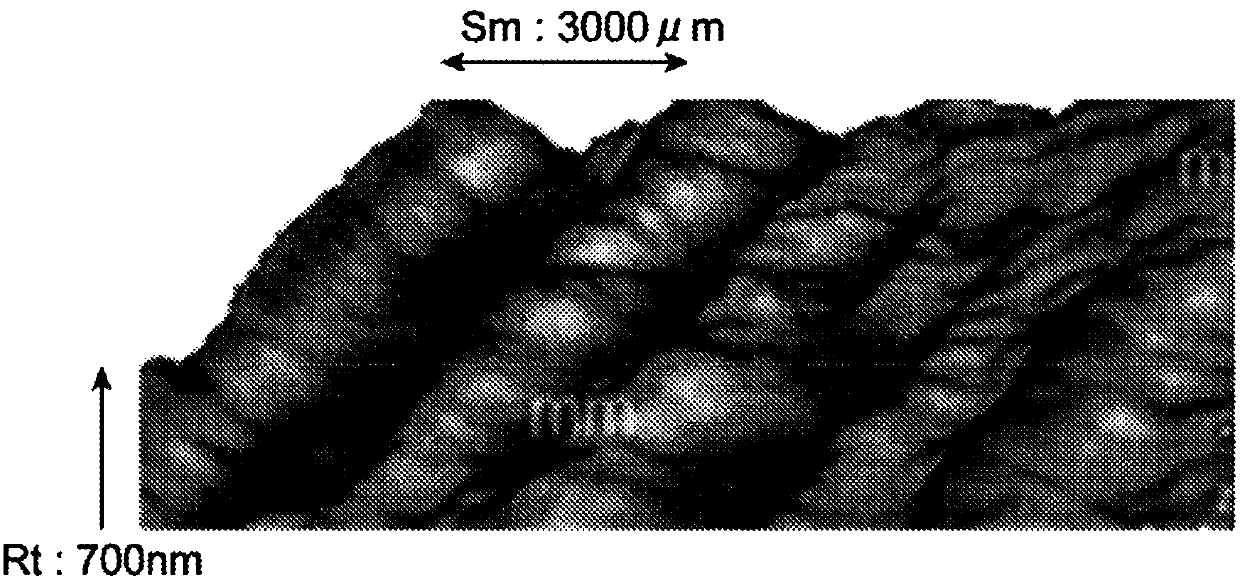
[0142] Except that the temperature of the first and second crosslinking steps was changed from 56°C to 59°C, and the total cumulative stretch ratio of the swelling, dyeing, crosslinking, and color correction steps was changed to 6.1 times, the same method as in Production Example 1 was produced. polarizer. (Unevenness of stripe pattern: Lv3, RSm=3700 μm, Rt=790 nm).

manufacture example 3

[0143]

[0144] In addition to changing the temperature of the first and second crosslinking steps from 56°C to 59°C, changing the boric acid in the crosslinking aqueous solution of the first and second crosslinking steps from 3% by weight to 3.6% by weight, and changing the swelling, A polarizing plate was produced in the same manner as in Production Example 1, except that the total cumulative draw ratio in the steps of dyeing, crosslinking, and color correction was changed to 6.3 times. (Unevenness of stripe pattern: Lv3, RSm=4900 μm, Rt=950 nm).


PUM

PropertyMeasurementUnit
surface roughnessaaaaaaaaaa
thicknessaaaaaaaaaa
thicknessaaaaaaaaaa

Abstract

A polarizing plate that includes: a polarizer in which the mean width of profile elements (RSm) is 500 to 5000 um and the maximum height of the roughness profile (Rt) is 100 to 1000 nm; an adhesive layer which is formed in a thickness of 250 to 850 nm on at least one surface of the polarizer; and a protective film which is laminated upon the adhesive layer.

Description

technical field [0001] The present invention relates to a polarizing plate excellent in both optical characteristics and appearance characteristics, a method for producing the same, and an image display device including the polarizing plate. Background technique [0002] Image display devices are commonly used electronic products such as clocks, mobile phones, PDAs, notebook computers, monitors for PCs, DVD players, TVs, and the like. A polarizing plate is used as a basic component of an image display device. [0003] In the manufacture of a polarizing plate, if the stretching ratio is increased in order to improve the orientation of the iodine complex of the polarizing plate for the purpose of improving the performance of the polarizing plate, the width of the polarizing plate will be reduced in the polarizing plate. Defective appearance such as unevenness of the stripe pattern occurs. [0004] Here, Patent Document 1 (Korean Laid-Open Patent No. 2014-0114923 ) discloses ...

Claims


Application Information

Patent Timeline
Patent Type & Authority Applications(China)
IPC IPC(8): G02B5/30H01L51/50H05B33/02
CPCG02B5/305G02B5/30H05B33/02H10K50/00B32B37/12B32B2329/04
Inventor 赵天熙朴重万崔正宁权容铉竹内智康
Owner SUMITOMO CHEM CO LTD
Why Eureka
Try Eureka