Flour bagging device

A bagging device, flour technology, applied in the direction of packaging, transportation and packaging, types of packaged items, etc., can solve a large number, continuous, adverse effects on the health of operators, increased air pressure, etc.

Inactive Publication Date: 2018-04-06
徐州苹果面粉有限公司
View PDF10 Cites 1 Cited by
  • Summary
  • Abstract
  • Description
  • Claims
  • Application Information

AI Technical Summary

Problems solved by technology

[0002] When bulk flour is bagged, since the bulk material will replace the original air in the packaging bag when it falls to the bottom of the packaging bag, some air will be brought in when the bulk material falls, and the original air and the scattered air will The air carried by the material into the packaging bag will accumulate in the packaging bag during the falling of the bulk material. Due to the continuous addition of bulk material, the space in the packaging bag will gradually become smaller, which will eventually lead to an increase in the air pressure in the packaging bag. This part of the air with relatively high pressure escapes directly from the air hole of the packaging bag or the gap of the opening of the bag, and the escape will carry a large amount of flour dust or fine materials in the bulk material, resulting in a large amount of continuous dust near the packaging bag. The dust or dusty air makes the air seriously polluted
This part of the polluted air will have an adverse effect on the health of the operating workers, which in turn will endanger the health of the operating workers

Method used


Image

  • Flour bagging device

Examples


Embodiment Construction

[0014] The present invention will be further described below in conjunction with accompanying drawing.

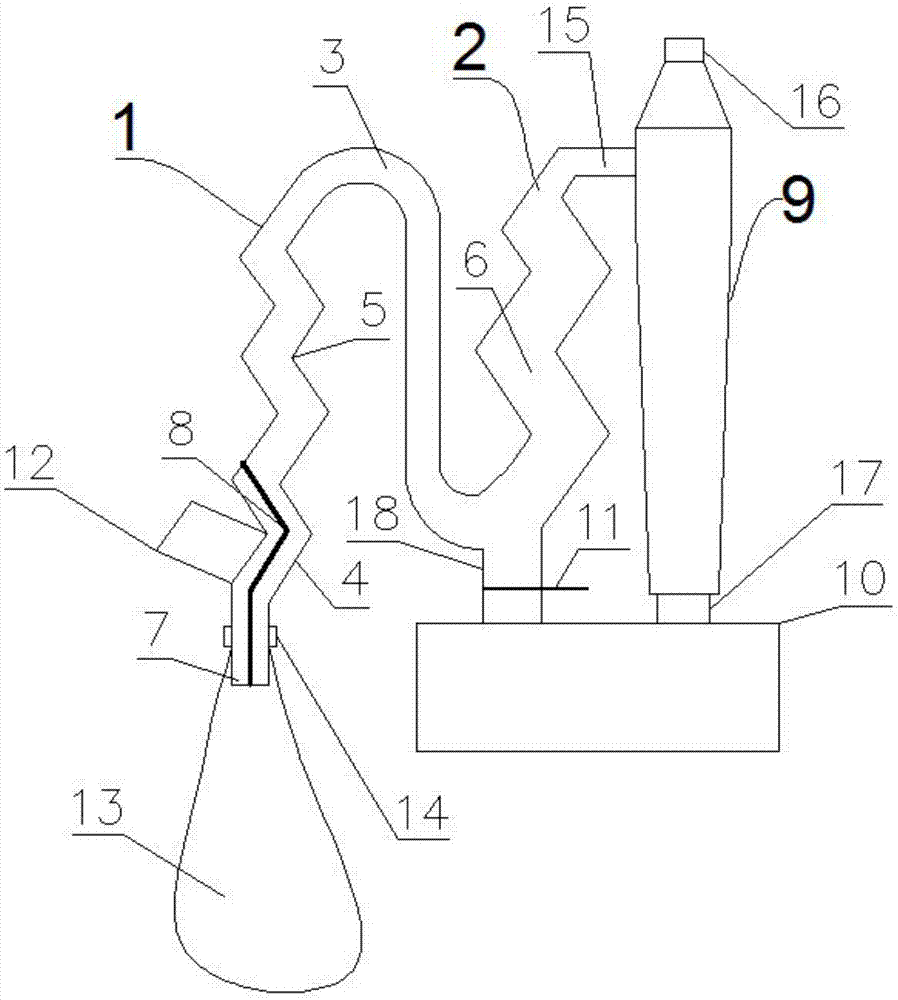
[0015] Such as figure 1 As shown, a flour bagging device includes a cyclone separator 13, a first separation pipeline 1, a second separation pipeline 2 and a drop tube between the first separation pipeline 1 and the second separation pipeline 2 Road 3, the cyclone separator 13 includes an inlet port 15, an air outlet port 16 and a solid material outlet port 17, and the first separation pipeline 1, the blanking pipeline 3 and the second separation pipeline 2 are all vertically arranged;

[0016] The first separation pipeline 1 is composed of a V-shaped pipeline 4 with the opening facing the left at the lower part and a W-shaped pipeline 5 with the opening facing the left at the upper part; the blanking pipeline 3 is S-shaped; the second separation pipe Road 2 is mainly composed of W-shaped pipeline 2 6 with the opening facing left;

[0017] The lower end of the first separ...


PUM


Abstract

The invention discloses a flour bagging device which comprises a first separation pipeline, a second separation pipeline and a falling pipeline located between the first separation pipeline and the second separation pipeline. The first separation pipeline is composed of a V-shaped pipeline located at the lower portion and a first W-shaped pipeline located at the upper portion. The falling pipe isin an S shape. The second separation pipeline is mainly composed of a second W-shaped pipeline. The lower end of the first separation pipeline is connected with a discharging pipeline which is vertically arranged. The upper end of the first separation pipeline is connected with the upper end of the falling pipeline, and the lower end of the falling pipeline is connected with the lower end of the second separation pipeline. The upper end of the second W-shaped pipeline is connected with the gas inlet end of a cyclone separator through a pipeline. A partition plate is arranged at the middle portion of the V-shaped pipeline and the middle portion of the discharging pipeline. The left side of the lower half section of the V-shaped pipeline is provided with a feeding pipeline communicating withan inner cavity of the V-shaped pipeline. The lower end of the falling pipeline is connected with a material collecting pipeline which is vertically arranged. The lower portion of the material collecting pipeline is provided with a shutter used for opening or closing an inner cavity of the material collecting pipeline. By means of the flour bagging device, dust or the dust-containing air amount generated in the bagging process can be effectively reduced.

Description

technical field [0001] The invention relates to flour processing equipment, in particular to a flour bagging device. Background technique [0002] When bulk flour is bagged, since the bulk material will replace the original air in the packaging bag when it falls to the bottom of the packaging bag, some air will be brought in when the bulk material falls, and the original air and the scattered air will The air carried by the material into the packaging bag will accumulate in the packaging bag during the falling process of the bulk material. Due to the continuous addition of bulk material, the space in the packaging bag will gradually become smaller, and eventually the air pressure in the packaging bag will increase. This part of the air with relatively high pressure escapes directly from the air hole of the packaging bag or the gap of the opening of the bag, and the escape will carry a large amount of flour dust or fine materials in the bulk material, resulting in a large amo...

Claims


Application Information

Patent Timeline
Patent Type & Authority Applications(China)
IPC IPC(8): B65B1/28B65B39/08
CPCB65B1/28B65B39/08
Inventor 刘延雷
Owner 徐州苹果面粉有限公司
Why Eureka
Try Eureka