Sponge city drainage structure and sponge city water circulation method

A technology of drainage structure and sponge city, applied in drainage structures, sewage removal, chemical instruments and methods, etc., can solve problems such as unfavorable urban drainage system operation, inability to connect water collection wells and drainage wells, etc.

Inactive Publication Date: 2018-04-06
安徽德司节能科技有限公司
View PDF2 Cites 3 Cited by
  • Summary
  • Abstract
  • Description
  • Claims
  • Application Information

AI Technical Summary

Problems solved by technology

[0003] The drainage structure of the sponge city in the prior art cannot well connect the water collection well and the drainage well, so that the water in the water collection well can be smoothly discharged into the drainage well, which is not conducive to the operation of the urban drainage system

Method used


Image

  • Sponge city drainage structure and sponge city water circulation method
  • Sponge city drainage structure and sponge city water circulation method
  • Sponge city drainage structure and sponge city water circulation method

Examples


Embodiment 1

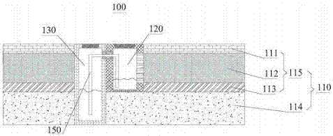
[0027] figure 1 A schematic structural diagram of a drainage structure 100 suitable for a sponge city provided in this embodiment. see figure 1 , in this embodiment, the drainage structure 100 includes a road layer structure 110 , a water collection well 120 and a drainage well 130 .

[0028] read on figure 1 , in this embodiment, the road layer structure 110 includes a permeable part 115 and a soil layer 114 from top to bottom, and the permeable part 115 includes a color permeable concrete layer 111, a high-permeability concrete layer 112 and a gravel grade from top to bottom. Layer 113. The colored permeable concrete layer 111 can not only satisfy people's desire for color and cultural atmosphere, but also has a beautiful appearance and appreciation; at the same time, it is conducive to the infiltration of surface water, improves the air permeability and water permeability of the surface, and has the function of regulating the temperature and humidity of the urban surface...

Embodiment 2

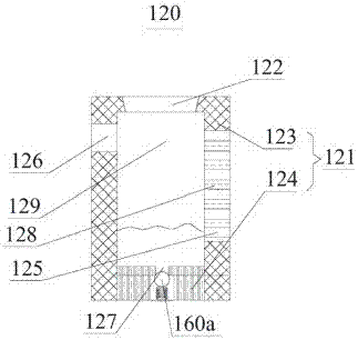
[0045] This embodiment provides a drainage structure 100 suitable for sponge cities. This embodiment is an improvement made on the basis of the technical solution in Example 1. The technical solution described in Example 1 is also applicable to this embodiment. 1 The disclosed technical solutions will not be described repeatedly. The difference between this embodiment and Embodiment 1 lies in the structure of the one-way valve 160b in this embodiment.

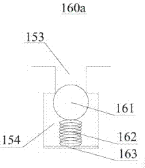
[0046] Figure 5 A structural schematic diagram of the one-way valve 160b in the drainage structure 100 suitable for the sponge city provided by this embodiment. read on Figure 5 , in this embodiment, the cross-sections of the upper opening 153 and the lower opening 154 are both rectangular, the spool 161 is a rectangular spool 261 , and the rectangular spool 261 is set at the junction of the upper opening 153 and the lower opening 154 . The cross-sectional area of ​​the upper opening 153 is smaller than the cross-sectional ...


PUM


Abstract

The invention discloses a movable narrow strip paper tape pressing mechanism, a control system and a control method, and belongs to the technical field of drainage structures. A sponge city drainage structure comprises a water collecting well, a drainage well and a road layer structure. The water collecting well comprises a water collecting well body. The water collecting well body comprises a side wall and a bottom wall connected with the side wall. A water collecting cavity is defined by the side wall and the bottom wall. The side wall is provided with a first opening and a second opening for being communicated with the road layer structure. The first opening and the second opening are arranged in a spaced mode and both run through the side wall. The drainage well is provided with a drainage cavity. A well wall of the drainage well is provided with a third opening. The water collecting cavity and the drainage cavity are communicated through a siphon pipe between the first opening andthe third opening. According to the drainage structure, the siphon pipe is arranged to make the water collecting cavity communicated with the drainage cavity, water in the water collecting cavity cansmoothly enter the drainage cavity, and the discharge of the water in the water collecting cavity is facilitated.

Description

technical field [0001] The invention belongs to the technical field of urban drainage, and in particular relates to a sponge city drainage structure and a sponge city water circulation method. Background technique [0002] Sponge city refers to a city that can be like a sponge and has good "elasticity" in adapting to environmental changes and responding to natural disasters. When it rains, it absorbs, stores, infiltrates, and purifies water, and "releases" the stored water when needed. and take advantage of it. Sponge city construction should follow the principles of ecological priority, combine natural approaches with artificial measures, and ensure the safety of urban drainage and waterlogging, maximize the accumulation, infiltration and purification of rainwater in urban areas, and promote the utilization of rainwater resources and ecological environment protection. In the process of sponge city construction, the systematic nature of natural precipitation, surface water...

Claims


Application Information

Patent Timeline
Patent Type & Authority Applications(China)
IPC IPC(8): E03F5/10E03F5/22E01C11/22E01C7/14E03F1/00C02F9/02
CPCE03F5/10C02F1/001C02F1/44C02F2103/001E01C7/14E01C11/226E03F1/00E03F5/105E03F5/22
Inventor 陈洪
Owner 安徽德司节能科技有限公司
Why Eureka
Try Eureka