
Reciprocating rotary type feeding and discharging temporarily-storing device and control method thereof
A technology of reciprocating rotation and buffering, applied in metal processing and other directions, can solve problems such as low production efficiency and positioning error, and achieve the effects of simple operation, low cost and simple structure
- Summary
- Abstract
- Description
- Claims
- Application Information
AI Technical Summary
Problems solved by technology
Method used
Image

Examples
Embodiment Construction
[0019] In order to more clearly illustrate the technical solutions of the embodiments of the present invention, the following will briefly introduce the accompanying drawings that need to be used in the description of the embodiments. Obviously, the accompanying drawings in the following description are only some embodiments of the present invention. For Those of ordinary skill in the art can also obtain other drawings based on these drawings without making creative efforts.
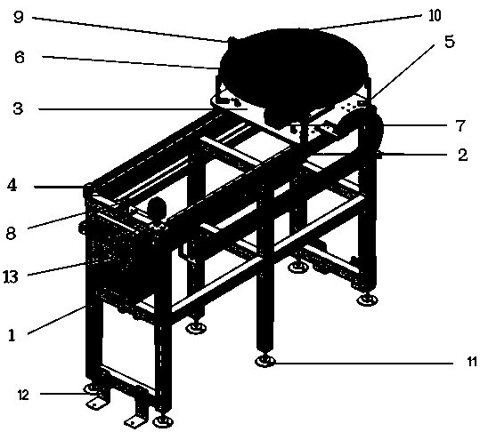
[0020] In the accompanying drawings, the list of parts represented by each label is as follows:
[0021] 1. Steel structure frame; 2. Linear guide rail; 3. Moving slide plate; 4. Rodless cylinder; 5. Part rack support mechanism; 6. Part rack; 7. Pneumatic indexing plate; Origin switch; 10, proximity sensor; 11, foot cup; 12, fixed corner piece.
[0022] figure 1 It shows the loading and unloading buffer device according to the present invention, which includes a steel structure frame 1, a linear guide...
PUM
 Abstract
Description
Claims
Application Information