Pneumatic tire

A pneumatic tire and bead technology, applied to the reinforcement layer of pneumatic tires, motorcycle tires, tire parts, etc., can solve the problems of inability to obtain lateral force and the impact of ground contact area, so as not to damage high-speed stability and realize lateral The effect of increasing force and lateral force

Inactive Publication Date: 2018-04-24
SUMITOMO RUBBER IND LTD
View PDF1 Cites 0 Cited by
  • Summary
  • Abstract
  • Description
  • Claims
  • Application Information

AI Technical Summary

Problems solved by technology

The contact patch affects the lateral force, so in this case, there is a concern that the initially desired lateral force cannot be obtained

Method used


Image

  • Pneumatic tire
  • Pneumatic tire
  • Pneumatic tire

Examples


Embodiment 1

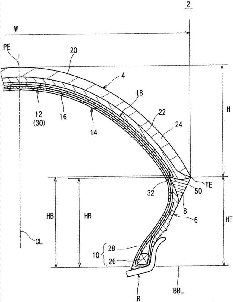
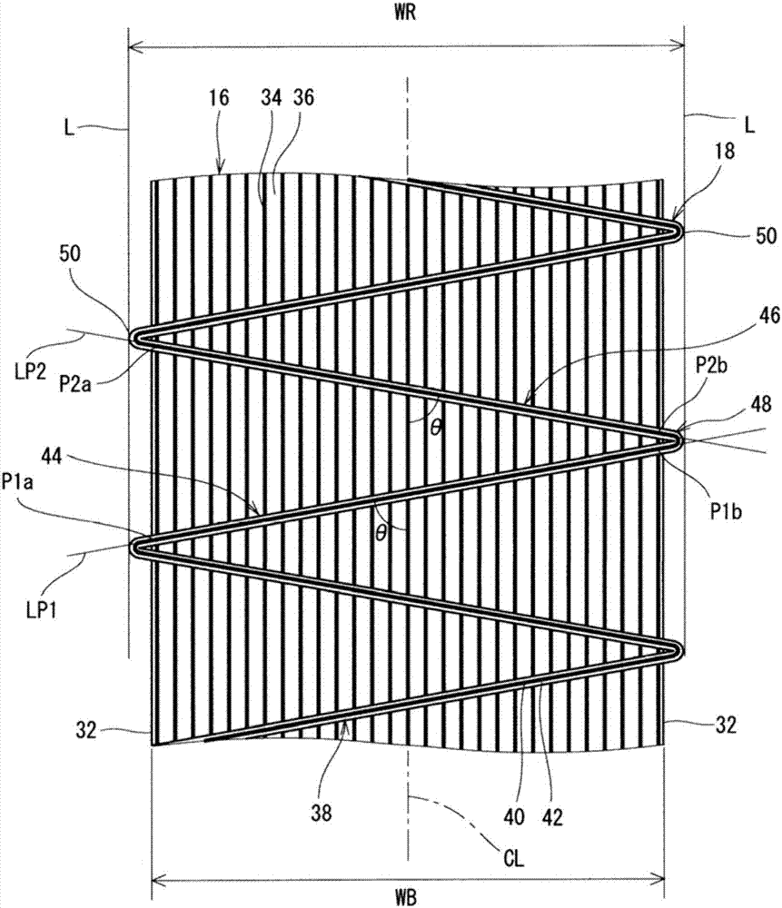
[0108] made figure 1 tires shown. The tire size is 190 / 55R17. In this Example 1, a figure 2 Reinforcing layers of the composition shown. In this Example 1, since the reinforcing layer is constituted by a strip wound once in the circumferential direction, this is indicated as "1" in the column of "Number of Laminations" in Table 1 below.

[0109] In this Example 1, the inclination angle θ of the reinforcing cord is set to 70°, and is set to be the same whether it is on the equatorial plane or on the shoulder portion. " and the column of "inclination angle θs" is represented by "70".

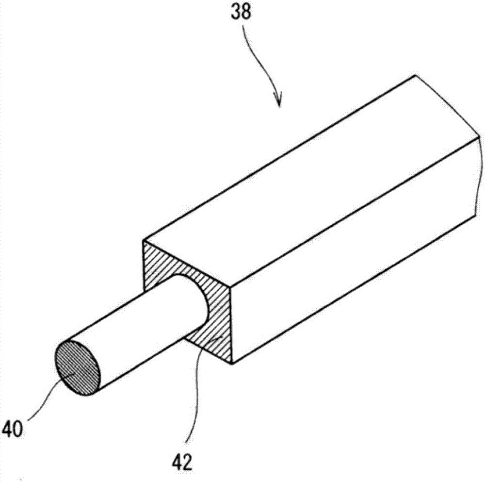
[0110] In this Example 1, a cord (composition = 880 dtex / 2) composed of aramid fiber was used as a reinforcing cord.

Embodiment 2

[0118] In addition to being used as a reinforcement layer with Figure 5 A reinforcing layer having the configuration shown was used, and the tires of Example 2 were obtained except that the inclination angle θc and the inclination angle θs were the same as those in Example 1 except as shown in Table 1 below.

Embodiment 3

[0120] In addition to being used as a reinforcement layer with Image 6 A reinforcing layer having the configuration shown was used, and the tire of Example 3 was obtained except that the inclination angle θc and the inclination angle θs were the same as in Example 1 except that they were as shown in Table 1 below.


PUM


Abstract

An object of the present invention is to provide a pneumatic tire 2 that can achieve improvement of a lateral force without reducing high-speed stability. In a tire 2, a band 16 has a jointless structure. A reinforcing layer 18 is layered over the band 16 from a radially outer side of the band 16. In the reinforcing layer 18, a reinforcing cord 40 is extended alternately on and between one end 32portion of the band 16 and the other end 32 portion of the band 16, so as to extend in the circumferential direction. A direction in which the reinforcing cord 40 extends is tilted relative to the circumferential direction between one of ends 32 of the band 16 and the other of the ends 32 of the band 16. An absolute value of an angle of the reinforcing cord 40 relative to the circumferential direction is greater than or equal to 70 DEG.

Description

technical field [0001] The present invention relates to pneumatic tires. Specifically, the present invention relates to a pneumatic tire for motorcycles. Background technique [0002] In tires for motorcycles, cap bands having a seamless structure are often used. The band cord contained in the band is wound helically. [0003] In the band, the band cords actually extend in the circumferential direction. In this crown, a large lateral force cannot be obtained. A tire with a small lateral force tends to have poor cornering performance. [0004] For example, a member including a plurality of cords arranged in parallel (hereinafter, referred to as a cut ply) contributes to the improvement of the lateral force of the tire. Accordingly, in tires having a cap band, the application of components including cords inclined with respect to the equatorial plane has been studied in order to improve cornering performance. An example of this research is disclosed in JP 2007-168474 A. ...

Claims


Application Information

Patent Timeline
Patent Type & Authority Applications(China)
IPC IPC(8): B60C9/18B60C9/22
CPCB60C9/1807B60C9/22B60C2009/2238B60C2009/2242B60C9/263B60C2009/2025B60C2009/2032B60C2009/266B60C9/20B60C2009/2022B60C2009/2096B60C2200/10
Inventor 小林弘之
Owner SUMITOMO RUBBER IND LTD
Why Eureka
Try Eureka