Automatic device before hoisting of wind turbine main shaft flange

A technology of automation device and wind power spindle, applied in the direction of conveyor control device, transportation and packaging, roller table, etc., can solve the problems of high cost of large-scale driving, increase of production cost, high risk, etc., achieve low noise, less error-prone, Excellent safety effect

Active Publication Date: 2019-08-13
JIANGYIN ZENKUNG FORGING CO LTD
View PDF7 Cites 0 Cited by
  • Summary
  • Abstract
  • Description
  • Claims
  • Application Information

AI Technical Summary

Problems solved by technology

Also have as application number is 201310673410.8 and application number is 201320365185.7 new type spreader, and it all is to make full use of the installation hole of flange itself to lift, but all exists the work of the installation hole alignment before lifting, and this work is still by the worker Manual operation (using a large crane plus a spreader, supplemented by manual collaboration to align the mounting holes), is inefficient, and the cost of a large crane is high, the volume is large, and with the increase in labor costs, it increases production. cost, and because workers operate directly next to the flange, it is dangerous

Method used


Image

  • Automatic device before hoisting of wind turbine main shaft flange
  • Automatic device before hoisting of wind turbine main shaft flange
  • Automatic device before hoisting of wind turbine main shaft flange

Examples


Embodiment 1

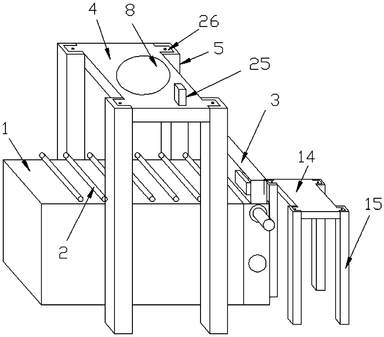
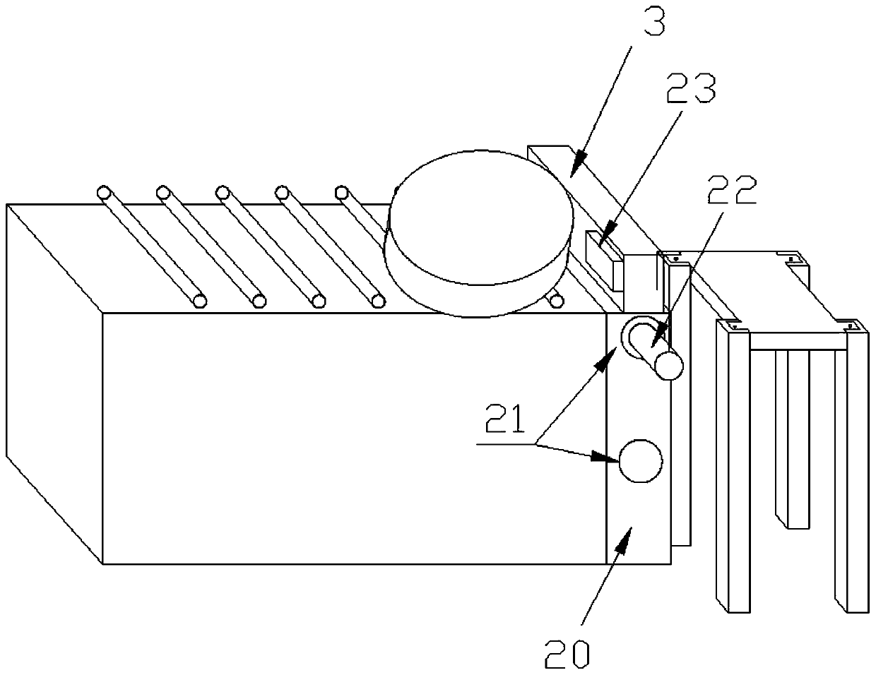
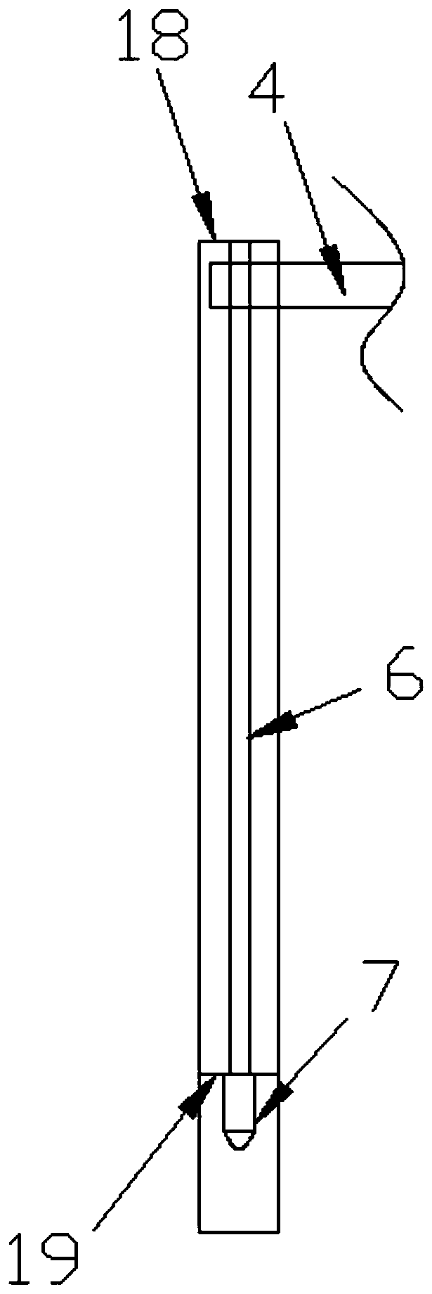
[0028] like Figure 1 to Figure 8 as shown ( figure 1 Flange and sleeve not shown, Figure 5 , Figure 7 , Figure 8Only one sleeve is shown, and the sleeve on the right side is not shown in the figure), the present invention is an automatic device for wind power main shaft flange hoisting, including a frame 1, and a flange is provided on the working surface of the frame 1 The conveying device 2, one end of the conveying direction of the frame 1 is provided with a limit baffle 3 that can slide up and down, and the height of the limit baffle 3 does not exceed the height of the flange; it also includes an orifice plate 4 arranged above the frame 1 The hole plate 4 is slidably arranged on the hole frame 5, and the hole frame 5 is provided with a first lifting screw 6 for driving the hole plate 4 to slide up and down and a first motor 7 for driving the first lifting screw 6 to rotate. , the orifice plate 4 is fixedly provided with a slider 26 adapted to the first lifting screw...

Embodiment 2

[0030] The difference from Embodiment 1 is that, as Figure 9 As shown, the lifting lead screw and the drive motor are also arranged under the limit baffle, so that all operations are fully mechanized, without manual labor, and realize full automation.


PUM


Abstract

The invention discloses an automation device for wind power spindle flanges before hoisting. The automation device comprises a frame, a conveying device, a limiting baffle, a hole aligning plate, a lifting screw rod, a first motor, a flange stacking and storing frame, a second lifting screw rod and a second motor, wherein the limiting baffle is not higher than the flange; the hole aligning plate is slidably arranged on the hole aligning frame; the lifting screw rod is arranged inside the hole aligning frame and is used for driving the hole aligning plate to slide downwards; the first motor isarranged inside the hole aligning frame and is used for driving the lifting screw rod to rotate; the hole aligning plate is connected with a disc-like rotating plate by virtue of a first thrust bearing; the rotating plate is fixedly connected with at least one pair of sleeves; the top wall of each sleeve is fixedly connected with a spring; each spring is fixedly connected with one hole aligning column which can slide inside the corresponding sleeve; each hole aligning column is rotationally connected with an idler wheel; the diameter of each hole aligning column is smaller than that of the corresponding idler wheel; the diameter of each sleeve is smaller than the hole diameter of each mounting hole in the wind power flange; the flange stacking and storing frame is used for stacking flangeplates; and the second lifting screw rod is used for driving the stacked flange plates to slide up and down. By using the automation device disclosed by the invention, manual operations for aligning the mounting holes before a plurality of flanges are hoisted are reduced, the labor intensity of a worker is alleviated, relatively high efficiency is achieved, and extremely good safety is realized.

Description

technical field [0001] The invention relates to an automatic device before hoisting of a wind power main shaft flange. Background technique [0002] At present, due to the large difference between the workpiece and the blank of the wind power flange, and the workpiece requires better comprehensive mechanical properties, the processing sequence is divided into blanking (sawing), heating, forging, reheating, ring grinding, stress relief annealing, Turning, drilling, manual chamfering. After the processing is completed, several wind power flanges of uniform specifications are generally stacked and lifted by hoisting slings. Since the flange has a center hole and mounting holes around the center hole, the lifting method is to manually wind the lifting wire rope around the wind power plant. After the position of the circular section of the flange is positioned, the lifting steel wire rope is connected to the lifting hook set on the loading equipment, and then the wind power flan...

Claims


Application Information

Patent Timeline
Patent Type & Authority Patents(China)
IPC IPC(8): B65G13/06B65G47/88B65G43/00
CPCB65G13/06B65G43/00B65G47/8815B65G2201/0214B65G2203/042
Inventor 刘圣祥翟建青戴洪法
Owner JIANGYIN ZENKUNG FORGING CO LTD
Why Eureka
Try Eureka