Mesh model Walsh modeling method for aircraft flutter analysis

A grid model, flutter analysis technique, used in aerospace and information fields

Active Publication Date: 2019-11-29
XIAN FEISIDA AUTOMATION ENG
View PDF7 Cites 0 Cited by
  • Summary
  • Abstract
  • Description
  • Claims
  • Application Information

AI Technical Summary

Problems solved by technology

[0006] In order to overcome the problem that the existing technology cannot effectively express the complex flutter model under the influence of aerodynamic force and strength changes, the present invention provides a method for modeling the aircraft flutter analysis grid model Walsh, which is selected in the aircraft body axis system Multiple grid points, under the influence of aerodynamic and strength changes such as different flight speeds, atmospheric densities, airflow environments, and different temperatures, the complex flutter grid model is represented according to the body shaft system decomposition method, and the installation of sensors is proposed according to the requirements of the model. According to the data and image recording requirements, the data is obtained through the effective flutter flight test, the excitation function is obtained through the measurement value of the airflow sensor, the vibration variable is approximated and equivalently described by the Walsh function, and the coordinates of the body axis are determined according to the identification method Solve the three axial vibration equations at the grid points, which solves the technical problem that the existing technology cannot effectively express the complex flutter model under the influence of aerodynamic force and strength changes

Method used


Image

  • Mesh model Walsh modeling method for aircraft flutter analysis
  • Mesh model Walsh modeling method for aircraft flutter analysis
  • Mesh model Walsh modeling method for aircraft flutter analysis

Examples


Embodiment Construction

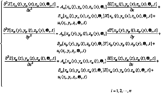
[0058] Step 1: Take the axis system of the aircraft body Analyzing complex flutter models, selecting grid points, the coordinates are: , when the vibration grid point coordinates for time and other two-axis position functions, in order to express the first grid points at The vibration component of the shaft, with For example, the subscript Label the grid point, the second letter of the subscript Respectively represent the vibration in the shafting of the body The three axis components of ; in order to simplify the problem, consider the first grid points at When vibrating in the axial direction, Consider the first grid points at When vibrating in the axial direction, , , considering the first grid points at When vibrating in the axial direction, ; For ease of writing, the , and abbreviated as , and ; The approximate model established in the neighborhood of grid points is:

[0059]

[0060] Formula 1

[0061] In the ...


PUM


Abstract

In order to overcome the problem in the prior art that a complex flutter model under aerodynamic force and strength change influences can not be effectively expressed, the invention provides an aircraft flutter analysis grid model Walsh modeling method. The method is characterized in that a plurality of grid points are selected in an aircraft engine body shaft system; under aerodynamic force and strength change influences including different flight speeds, atmospheric densities, airflow environments, different temperatures and the like, according to an engine body shaft system decomposition method, a complex flutter grid model is expressed; according to a requirement for establishing the model, the requirements of installing sensors and data and image records are put forward; through an effective flutter flight experiment, data is obtained, and an excitation function is obtained through a measured value of an airflow sensor; a Walsh function is adopted to carry out approximation and equivalent description on a vibration variable; according to a distinguishing method, the solving of three axial vibration equations on an engine body axial system coordinate grid point can be simultaneously determined, and the technical problem in the prior art that the complex flutter model under aerodynamic force and strength change influences can not be effectively expressed is solved.

Description

technical field [0001] The invention relates to a ground comprehensive test method for flight safety of civil aircraft, fighter jets, unmanned aerial vehicles and the like, in particular to a flutter analysis grid model Walsh modeling method for aircraft, and belongs to the field of aerospace and information technology. Background technique [0002] Flutter is a large-amplitude vibration phenomenon that occurs when an elastic structure is coupled by aerodynamic, elastic, and inertial forces in a uniform airflow. For aircraft, vibration occurs after an uncertain disturbance in flight. At this time, due to the effect of the airflow, the elastic structure of the aircraft such as the wing, empennage or control surface will generate additional aerodynamic force; as an exciting force, the additional aerodynamic force will aggravate the vibration of the structure. At the same time, the damping force of the air on the aircraft structure tries to weaken the vibration; when flying at...

Claims


Application Information

Patent Timeline
Patent Type & Authority Patents(China)
IPC IPC(8): G06F17/50
CPCG06F30/15G06F30/20Y02T90/00
Inventor 史忠科
Owner XIAN FEISIDA AUTOMATION ENG
Why Eureka
Try Eureka