Ultra wide band radiation unit applied to low-frequency band antenna

A radiation unit and ultra-broadband technology, applied in the field of ultra-broadband radiation unit, can solve the problems of small bandwidth and large caliber of radiation unit, and achieve the effect of large bandwidth, durable structure and compact structure

Pending Publication Date: 2018-08-28
JIANGSU JST RF SYST
View PDF0 Cites 4 Cited by
  • Summary
  • Abstract
  • Description
  • Claims
  • Application Information

AI Technical Summary

Problems solved by technology

[0003] Purpose of the invention: The present invention provides an ultra-wideband radiation unit applied to low-frequency antennas, which solves the problem of large caliber and small bandwidth of the existing radiation unit

Method used


Image

  • Ultra wide band radiation unit applied to low-frequency band antenna
  • Ultra wide band radiation unit applied to low-frequency band antenna
  • Ultra wide band radiation unit applied to low-frequency band antenna

Examples


Embodiment Construction

[0026] The present invention will be further described below in conjunction with accompanying drawing.

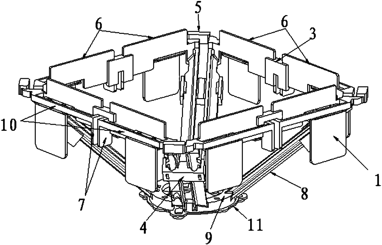
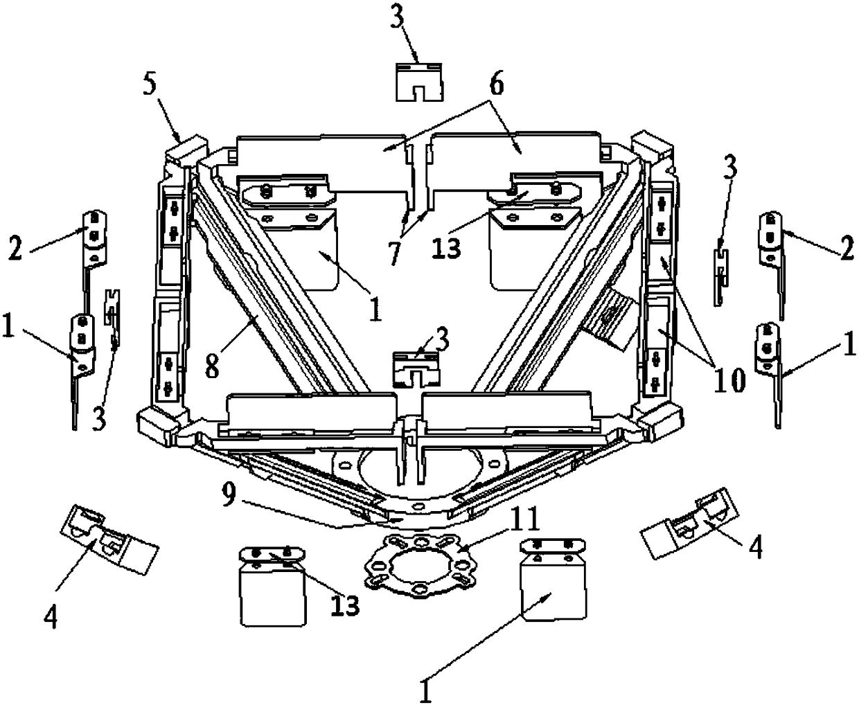
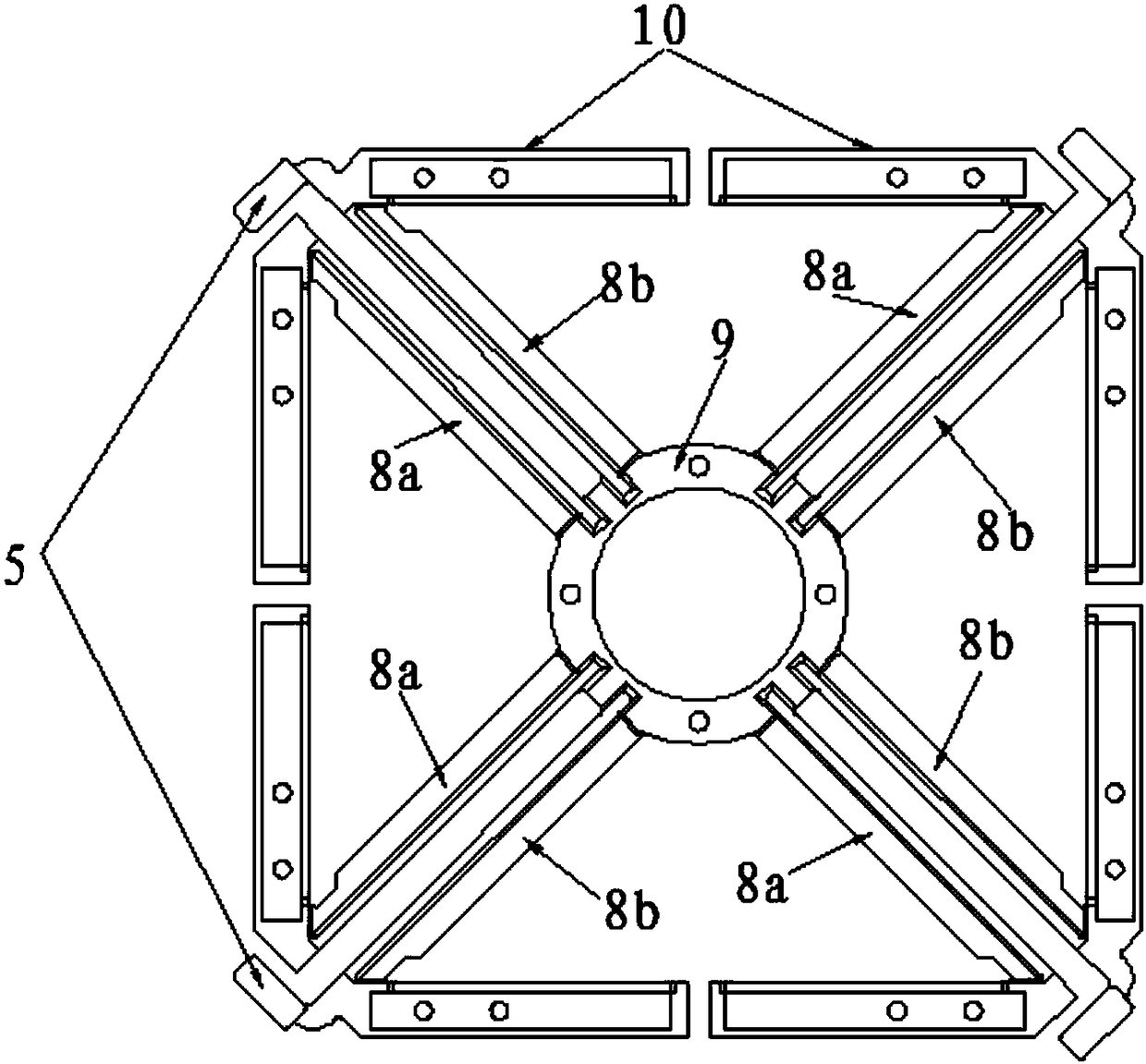
[0027] Such as Figure 1-9 As shown, an ultra-broadband radiation unit includes four radiators surrounded by a square radiator, the radiation directions of two adjacent radiators are vertical, a base 9 is connected to the bottom of the radiator through a support member 8, and one end of the support member 8 is set It is connected to the radiation arm 10 at the angle of the square radiator, and the other end is connected to the base 9. The supporting part 8 and the base form an angle of 40° to 50°. The supporting part 8 extends from the bottom of the base 9 to the radiator. The caliber is surrounded by four supporting parts 8 and presents a tendency of enlargement. The radiator includes a radiation arm 10, a resonator 6 and a coupling piece 1. The resonator 6 and the coupling piece 1 are vertically arranged on the radiation arm 10. A groove is provided on the horizontal surf...


PUM


Abstract

The present invention discloses an ultra wide band radiation unit applied to a low-frequency band antenna. The ultra wide band radiation unit comprises radiators having radiation directions which areperpendicular to each other, the lower portions of the radiators are connected with a pedestal through support parts, each radiator comprises one radiation arm, one resonance body and one coupling sheet, the resonance bodies and the coupling sheets are vertically arranged on the radiation arms, and the horizontal planes of the radiation arms are provided with grooves. The ultra wide band radiationunit is compact in structure, large in bandwidth, good in radiation index, firm and durable in structure, wide in application range, high in universality and good in production consistency; and antenna formed based on the radiators has good radiation features.

Description

technical field [0001] The invention relates to an antenna radiation unit, in particular to an ultra-wideband radiation unit applied to a low-frequency antenna. Background technique [0002] In the cellular mobile communication system, the antenna is the converter of the circuit signal of the communication equipment and the space radiation electromagnetic wave, and is the bridgehead of the space wireless communication. Therefore, the base station antenna is an important part of the mobile communication system, and its characteristics directly affect the overall performance of the entire wireless network. . At present, domestic and foreign telecom operators need different types of antennas to meet their network construction requirements; secondly, the difficulty of site selection is gradually increasing for each operator when building a network. All of these pose new challenges to the development of base station antennas. How to improve the versatility of base station antenn...

Claims


Application Information

Patent Timeline
Patent Type & Authority Applications(China)
IPC IPC(8): H01Q1/36H01Q1/50H01Q19/10H01Q21/08H01Q21/30
CPCH01Q1/36H01Q1/50H01Q19/106H01Q21/08H01Q21/30
Inventor 苏燕奎王金广唐鹏黄平王炳烽
Owner JIANGSU JST RF SYST
Why Eureka
Try Eureka