Novel garbage can capable of automatically sorting
A technology of automatic classification and trash cans, which is applied in the direction of trash cans, garbage collection, waste collection and transfer, etc., and can solve the problem of single function
- Summary
- Abstract
- Description
- Claims
- Application Information
AI Technical Summary
Problems solved by technology
Method used
Image

Examples
Embodiment Construction
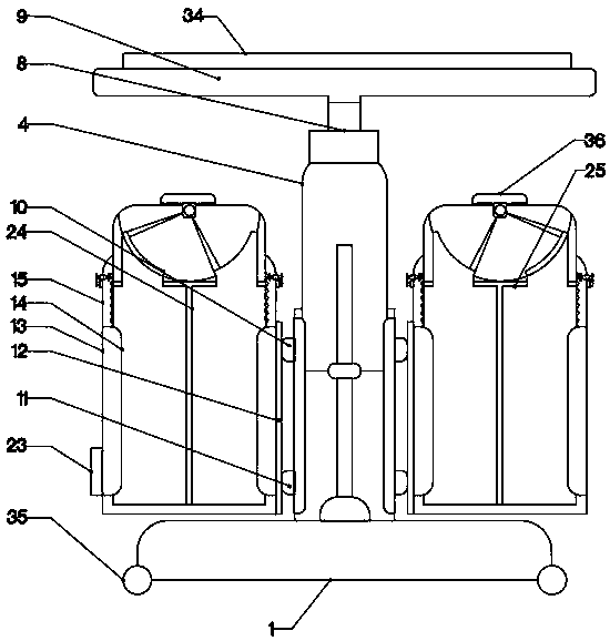
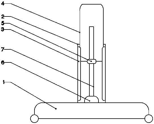
[0021] The present invention is specifically described below in conjunction with accompanying drawing, as Figure 1-5 As shown, it includes a rectangular base 1, and a telescopic device is arranged above the rectangular base 1. The telescopic device consists of a vertical support rod 2 fixedly connected to the rectangular base 1 at the center of the upper surface of the rectangular base 1, and a vertical The inner surface of the support rod 2 and the rectangular chute 3 that is fixedly connected to the vertical support rod 2 in the vertical direction, the rectangular telescopic rod 4 that is slidably connected to the rectangular chute 3 on one side of the rectangular chute 3, and the rectangular telescopic rod 4 that is located on the rectangular chute 3 The inner threaded block 5 embedded in the center of the lower surface and connected to the rectangular telescopic rod 4, the rotating motor 1 fixedly connected to the vertical supporting rod 2 at the center of the lower surfac...
PUM
 Abstract
Description
Claims
Application Information
 - R&D
- Intellectual Property
- Life Sciences
- Materials
- Tech Scout
- Unparalleled Data Quality
- Higher Quality Content
- 60% Fewer Hallucinations
Browse by: Latest US Patents, China's latest patents, Technical Efficacy Thesaurus, Application Domain, Technology Topic, Popular Technical Reports.
© 2025 PatSnap. All rights reserved.Legal|Privacy policy|Modern Slavery Act Transparency Statement|Sitemap|About US| Contact US: help@patsnap.com