Spectral imaging system with large field of view using variable-diameter fiber-optic field-of-view splitter

A field of view splitter and spectral imaging technology, which is applied in the field of imaging spectrum, can solve the problems of increased space size, increased detector cost, and limited layout space, and achieves the effect of easy downscaling and strong designability

Active Publication Date: 2020-09-01
CHANGCHUN INST OF OPTICS FINE MECHANICS & PHYSICS CHINESE ACAD OF SCI
View PDF5 Cites 0 Cited by
  • Summary
  • Abstract
  • Description
  • Claims
  • Application Information

AI Technical Summary

Problems solved by technology

The more direct way is to directly optically register the object plane of the spectrometer with the image plane of the telescopic system, which requires a large spatial dimension of the image plane of the spectrometer, and requires a high-performance large-size detector to realize it. The demand increases, the cost of detectors increases exponentially, and it is not even technically available
Another method in the push-broom mode is the technical means of realizing knife-edge segmentation of the field of view. This method requires a high-precision knife-edge mirror. In addition, there are also situations in which the subsequent optical system has a large space and limited layout space. The field of view The further increase of , the scheme will become extremely complicated, and the space size will be doubled or even impossible to realize
Therefore, the current technical solution can only meet the observation requirements of a large field of view to a certain extent, and cannot become an ideal technical solution for airborne or spaceborne resource requirements.

Method used


Image

  • Spectral imaging system with large field of view using variable-diameter fiber-optic field-of-view splitter
  • Spectral imaging system with large field of view using variable-diameter fiber-optic field-of-view splitter

Examples


Embodiment Construction

[0020] In order to make the object, technical solution and advantages of the present invention clearer, the present invention will be further described in detail below in conjunction with the accompanying drawings and specific embodiments. It should be understood that the specific embodiments described here are only used to explain the present invention, but not to limit the present invention.

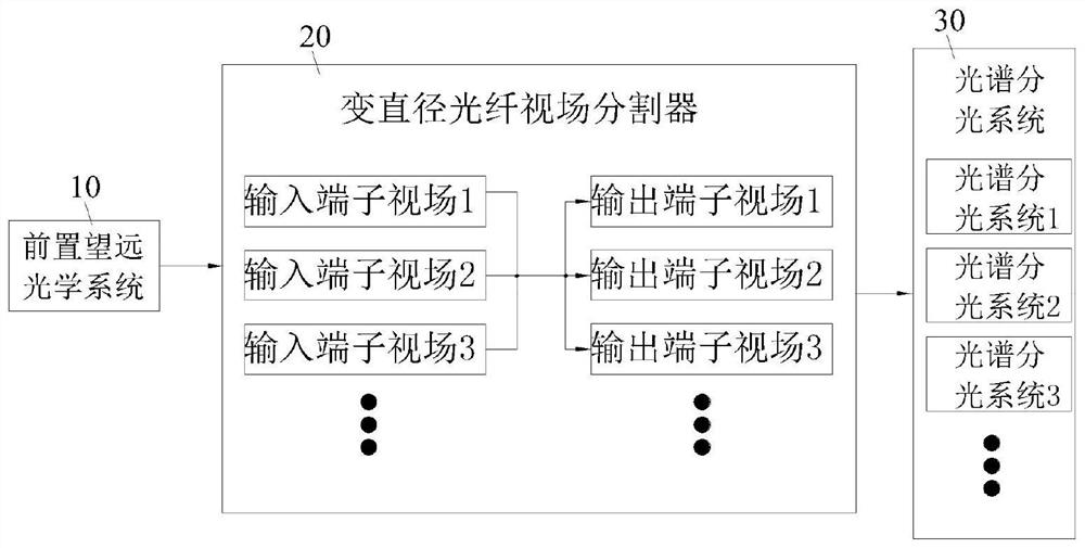
[0021] see figure 1 , The embodiment of the present invention provides a spectral imaging system that uses a variable-diameter optical fiber field of view splitter to achieve a large field of view.

[0022] The front telescopic optical system 10 is used for collecting spectral information of a large field of view at its focal plane.

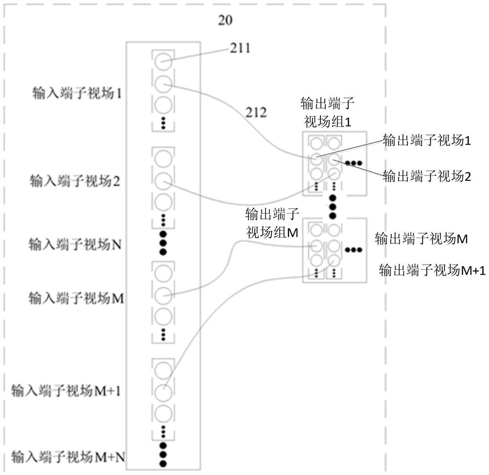
[0023] The variable-diameter optical fiber field of view splitter 20 includes a large field of view at the input end and multiple sets of field of view output terminal groups. The large-size line field of view of the front-end telescopic imaging system e...


PUM


Abstract

The invention discloses a spectral imaging system that adopts a variable-diameter optical fiber field of view splitter to realize a large field of view. Splitter, including multiple sets of input terminal field of view, multiple sets of output terminal field of view groups and variable-diameter fiber bundles, the large-size linear field of view of the front telescopic imaging system is divided into multiple sets of input terminal fields of view, and multiple sets of output terminals The field of view group is reorganized, and multiple sets of output terminal field of view groups are connected to the spectral spectroscopic system; the spectral spectroscopic system is used to splicing the spectral imaging bands of multiple sets of output terminal field of view groups to form a complete large Field of view imaging spectral information. The invention can optically divide and recombine a large field of view into small field groups, reduces the size requirement of a large-scale line field of view for a spectral detection system, and facilitates the miniaturization of spectroscopic elements and detector elements and the integration of imaging spectral systems.

Description

technical field [0001] The invention relates to the technical field of imaging spectrum, in particular to a spectral imaging system that adopts a variable-diameter optical fiber field of view splitter to realize a large field of view. Background technique [0002] With the continuous improvement of the informatization level of today's society, space remote sensing information has become an important social and economic resource. The detection and development in the fields of aerial surveying and mapping, environmental monitoring, resource detection and many other monitoring tasks related to the national economy and the people's livelihood need to be based on space remote sensing information. Conventional satellites and high-altitude aerial remote sensing have played an important role in earth observation, but it is difficult to meet the needs of many emergency dynamic investigations and monitoring that require high resolution and fast time. From the perspective of applicati...

Claims


Application Information

Patent Timeline
Patent Type & Authority Patents(China)
IPC IPC(8): G01J3/28G01J3/02G01J3/04
CPCG01J3/0289G01J3/04G01J3/2823
Inventor 郑玉权王龙高明辉纪振华韦跃峰薛浩蔺超
Owner CHANGCHUN INST OF OPTICS FINE MECHANICS & PHYSICS CHINESE ACAD OF SCI
Why Eureka
Try Eureka