
Pulling-out tool

A tool and component technology, applied in the field of pulling tools, can solve problems such as the difficulty in aligning the pulling hook and the pulling hole

Active Publication Date: 2018-11-13
CHINA AVIATION OPTICAL-ELECTRICAL TECH CO LTD
View PDF10 Cites 1 Cited by
  • Summary
  • Abstract
  • Description
  • Claims
  • Application Information

AI Technical Summary

Problems solved by technology

[0005] The present invention aims to provide a pulling tool to solve the problem of difficult alignment of the pulling hook and the pulling hole in the prior art

Method used


Image

  • Pulling-out tool
  • Pulling-out tool
  • Pulling-out tool

Examples


Embodiment Construction

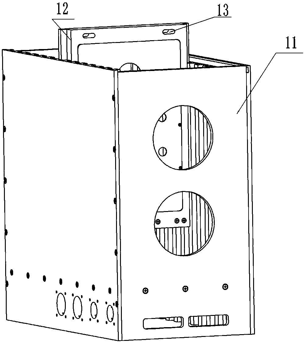
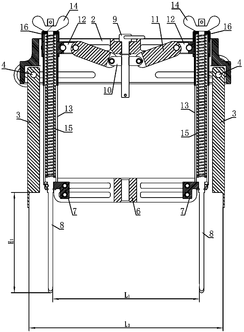
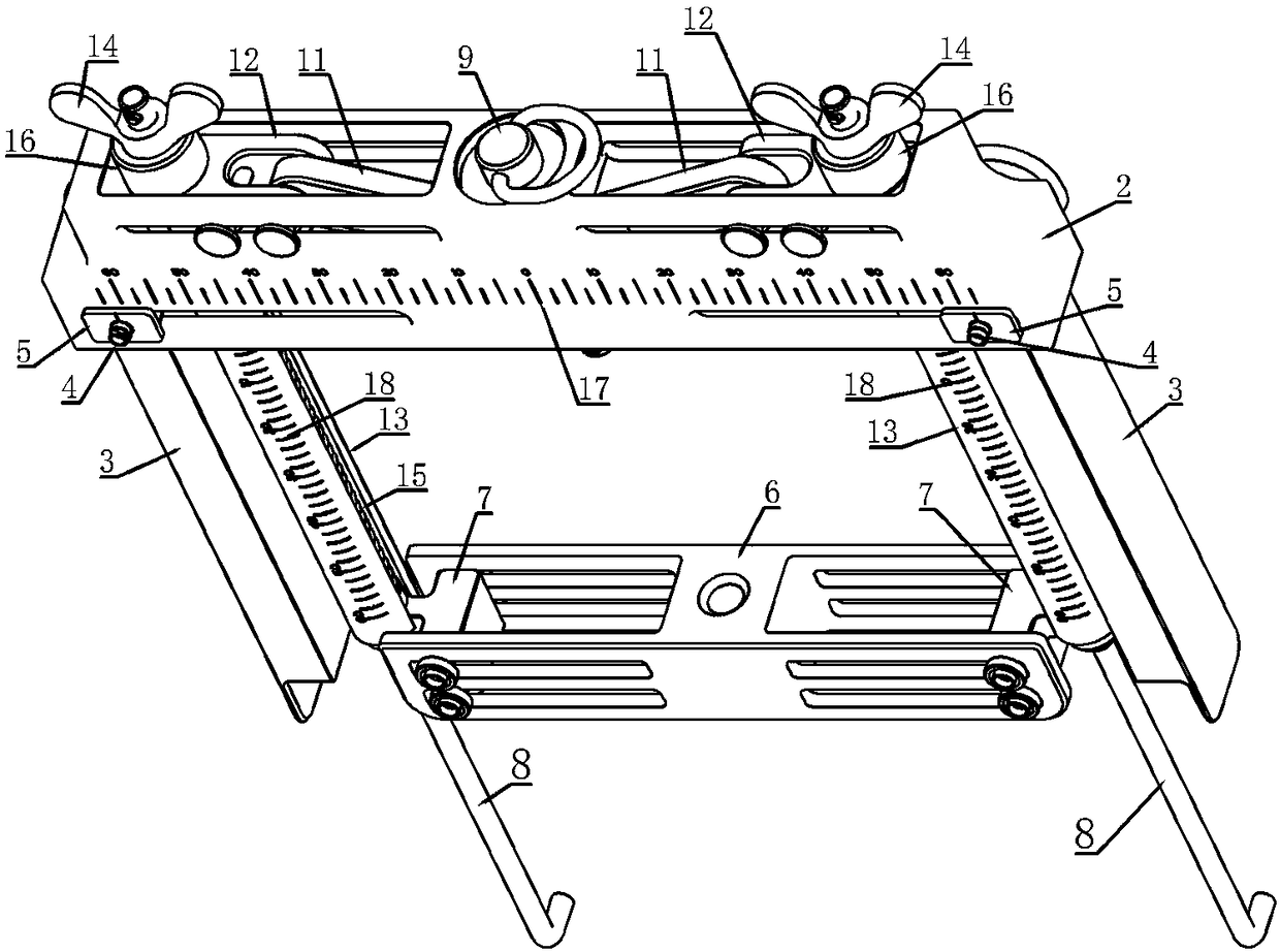
[0033] Embodiment of the pulling tool in the present invention: the pulling tool is an industrial-grade adjustable pulling tool suitable for pulling out a functional module from a chassis, such as figure 2 with image 3 As shown, the pulling tool is mainly composed of a support frame, a pulling part, a distance adjustment mechanism, and a depth adjustment mechanism. Lifting holes with a wide spacing; under the adjustment of the depth adjustment mechanism, it can be adapted to the lifting holes of different depths in the box on the functional module.

[0034] The support frame is mainly composed of a support 2 and legs 3 symmetrically arranged on the left and right sides thereof.

[0035] Such as Figure 4 As shown, the support 2 is a left-right symmetrical box structure with respect to a reference elevation extending forward and backward. The direction and the thickness direction are in the up-down direction. The support 2 is divided into an upper box body 201 and a lower...


PUM


Abstract

The invention relates to a pulling-out tool. The pulling-out tool comprises a driving mechanism for outputting a forward and reverse linear reciprocating motion or a forward and reverse rotary reciprocating motion by an output end, and two synchronous transmission mechanisms in transmission connection between the output end of the driving mechanism and two pulling-out parts; and at least one of the driving mechanism, the synchronous transmission mechanisms and the pulling-out parts is provided with locking structures for locking left and right positions of the two pulling-out parts. The linearreciprocating motion or the rotary reciprocating motion output by the driving mechanism is actually used as input; and the two synchronous transmission mechanisms synchronously convert the input intotwo opposite output to drive the two pulling-out parts to oppositely move synchronously, so that the gap width between drawing hooks of the two pulling-out parts is adjusted in a manner of oppositelyand synchronously moving the two pulling-out parts relative to the driving mechanism, and the pulling-out tool has the advantages of convenient alignment and smooth pulling out.

Description

[0001] This application is a divisional application of the following application, the filing date of the original application: September 21, 2016, the application number of the original application: 201610837376.7, the invention name of the original application: a pulling tool. technical field [0002] The invention relates to a pulling tool. Background technique [0003] At present, in industrial production, such as figure 1 As shown in the case, the case includes a box body 11 with an opening at the top, inside the box body 11 are assembled a plurality of functional modules 12 spaced from front to back, and the left and right sides of each functional module 12 are guided to move up and down and assembled on the side of the box body 11. On the side wall, and on the front side of each functional module 12, there are two lifting holes 13 at the top, and there are two lifting holes 13, which are symmetrically arranged on the left and right sides of the front side, and the two ...

Claims


Application Information

Patent Timeline
Patent Type & Authority Applications(China)
IPC IPC(8): B25B27/02
CPCB25B27/02
Inventor 王建雨
Owner CHINA AVIATION OPTICAL-ELECTRICAL TECH CO LTD
Features
  • Generate Ideas
  • Intellectual Property
  • Life Sciences
  • Materials
  • Tech Scout
  • Unparalleled Data Quality
  • Higher Quality Content
  • 60% Fewer Hallucinations
Learn More