a puller

A puller and guide technology, which is applied to hand-held tools, manufacturing tools, etc., can solve the problem of easy deflection of the puller, and achieve the effect of avoiding deflection

Active Publication Date: 2018-02-16
中航光电互连科技(南昌)有限公司
View PDF10 Cites 0 Cited by
  • Summary
  • Abstract
  • Description
  • Claims
  • Application Information

AI Technical Summary

Problems solved by technology

[0004] The present invention aims to provide a puller to solve the problem in the prior art that the puller hook is easy to deflect when shifting

Method used


Image

  • a puller
  • a puller
  • a puller

Examples


Embodiment Construction

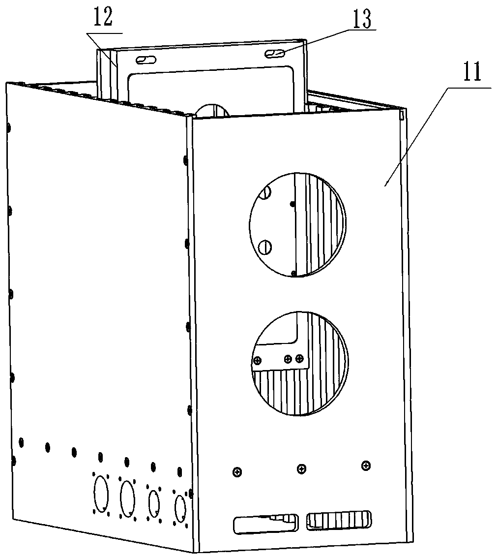
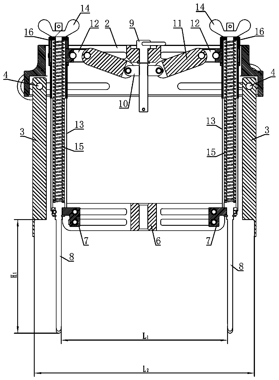
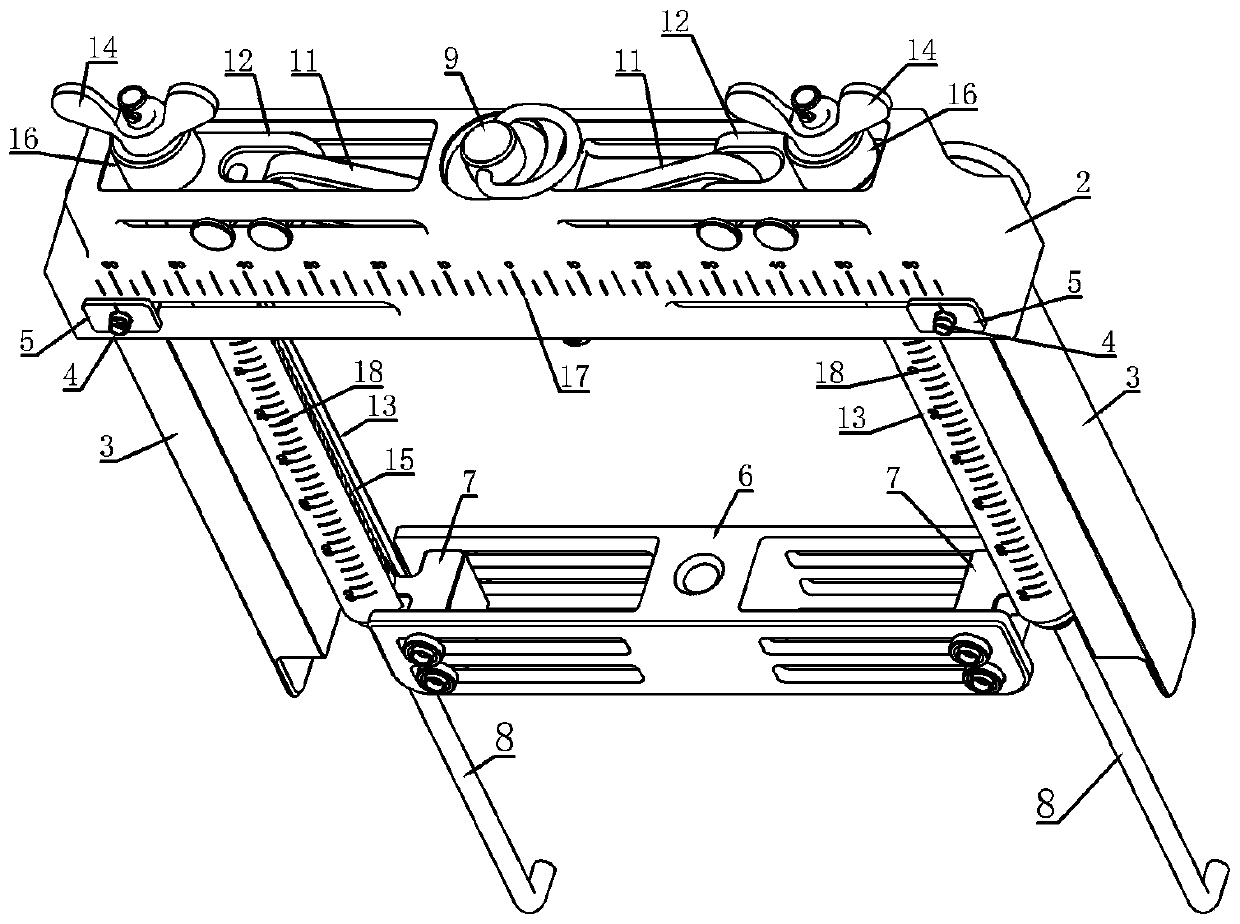
[0033] Embodiment of the puller in the present invention: the puller is an industrial-grade adjustable puller suitable for pulling out a functional module from a chassis, such as figure 2 and image 3 As shown, the puller is mainly composed of a support frame, a pulling part, a distance adjustment mechanism, and a depth adjustment mechanism. Lifting holes with a wide spacing; under the adjustment of the depth adjustment mechanism, it can be adapted to the lifting holes of different depths in the box on the functional module.

[0034] The support frame is mainly composed of a support 2 and legs 3 symmetrically arranged on the left and right sides thereof.

[0035] Such as Figure 4As shown, the support 2 is a left-right symmetrical box structure with respect to a reference elevation extending forward and backward. The direction and the thickness direction are in the up-down direction. The support 2 is divided into an upper box body 201 and a lower box body 202 which are in...


PUM


Abstract

The invention relates to an extractor. The extractor comprises a support frame, a handle and two extraction hooks, wherein the two extraction hooks both extend along the upward-downward direction; the two extraction hooks are provided with handle guide parts which are movably assembled on the handle along the leftward-rightward direction, and bracket guide parts which are movably assembled on the support frame along the leftward-rightward direction; the handle guide parts and the bracket guide parts are arranged at intervals one above the other on the extraction hooks; at least one of the handle guide parts and the bracket guide parts is in limiting fit with the support frame or the handle along the upward-downward direction. Actually, upper and lower guide positions which are away from each other are formed on the extraction hooks, the handle guide parts and the bracket guide parts can provide guiding support from two positions of the extraction hooks during adjustment of the left and right positions of the extraction hooks, and the extraction hooks are prevented from being deviated by taking any of the handle guide parts and the bracket guide parts as a supporting point by means of mutual constraint of the guiding support at the two positions, so that the two extraction hooks can move leftwards and rightwards in a parallel state.

Description

technical field [0001] The invention relates to a puller. Background technique [0002] At present, in industrial production, such as figure 1 As shown in the case, the case includes a box body 11 with an opening at the top, inside the box body 11 are assembled a plurality of functional modules 12 spaced from front to back, and the left and right sides of each functional module 12 are guided to move up and down and assembled on the side of the box body 11. On the side wall, and on the front side of each functional module 12, there are two lifting holes 13 at the top, and there are two lifting holes 13, which are symmetrically arranged on the left and right sides of the front side, and the two lifting holes 13 The center of symmetry is on the center line of the box body 11 , that is, the two extraction holes 13 are symmetrically arranged on the left and right sides of the box body 11 . [0003] When it is necessary to pull out the functional module from the box for maintena...

Claims


Application Information

Patent Timeline
Patent Type & Authority Patents(China)
IPC IPC(8): B25B27/02
CPCB25B27/02
Inventor 王建雨
Owner 中航光电互连科技(南昌)有限公司
Why Eureka
Try Eureka