Gas turbine combustor

a combustor and gas turbine technology, applied in the direction of hot gas positive displacement engine plants, combustion processes, lighting and heating apparatus, etc., can solve the problems of inability to achieve uniform mixing of premixed air-fuel mixtures with even concentration distribution, short premixing length, and inability to idealize leaned premixing combustion, etc., to facilitate the mixing of compressed air and fuel, facilitate the premixing, and facilitate the effect of further premixing

Inactive Publication Date: 2014-07-03
KAWASAKI HEAVY IND LTD
View PDF14 Cites 24 Cited by
  • Summary
  • Abstract
  • Description
  • Claims
  • Application Information

AI Technical Summary

Benefits of technology

[0010]According to the above described construction, in the inflow passage the compressed air and the fuel fed from the plurality of the fuel supply holes are supplied in a direction perpendicular to each other. Accordingly, by the action of a shearing force of the compressed air relative to the fuel, the mixing of the compressed air with the fuel is facilitated. Also, since the premixed air-fuel mixture is deflected 90° at the time it is introduced from the inflow passage into the premixing passage, a large turbulence occurs in the flow and the premixing is therefore facilitated. In addition, since the premixed air-fuel mixture is guided through the premixing passage in a direction axially upstream thereof, the premixing is further facilitated within this premixing passage. As a result, the uniform premixed air-fuel mixture having a minimized variation in concentration of the fuel can be obtained. Since this premixed air-fuel mixture is injected into the combustion chamber through the plurality of the premixed air-fuel mixture injection holes, a bias of the premixed air-fuel mixture within the combustion chamber is suppressed. Also, since the premixed air-fuel mixture is injected into the combustion chamber from the main burner of the premixing type disposed in an outer periphery of the pilot burner, the uniformly premixed air-fuel mixture having a minimized variation in concentration of the fuel, not the air-fuel mixture having an enriched concentration, is combusted within the combustion chamber over the entire operating region ranging from a low load operating region to a high load operating region. In view of this, the emissions of NOx may be reduced.
[0011]In one embodiment of the present invention, a fuel injection hole may be provided at a center portion of the pilot burner to inject a portion of a fuel for piloting purpose into the combustion chamber. According to this structural feature, since that portion of the fuel for the pilot burner can be injected into the combustion chamber through the fuel injection hole provided at the center portion of the pilot burner, the ignitability may be increased and a flame stability can be secured.
[0012]In one embodiment of the present invention, a carbon removal injection hole may be formed in the vicinity of a downstream side of the fuel injection hole to supply a portion of the premixed air-fuel mixture within the premixing passage. According to this structural feature, the concentration of the fuel injected through the fuel injection hole into the combustion chamber may be made lower by means of the premixed air-fuel mixture from the carbon removal injection hole to there by avoid an undesirable generation of soot (carbon) which would be brought about by the excessive enrichment of the fuel. Accordingly, the fuel may be stably injected into the combustion chamber without allowing the fuel injection hole to be clogged with a deposition of carbon.
[0013]In one embodiment of the present invention, the premixing passage may include a speed increasing portion having a passage section that gradually reduces towards a downstream side. According to this structural feature, the flow through the speed increasing portion results in an increase of the flow velocity of the premixed air-fuel mixture and, therefore, it is possible to avoid an undesirable back fire from occurring from the side of the combustion chamber to the premixing passage.
[0014]In one embodiment of the present invention, a mixing facilitation member may be provided on an upstream side of the speed increasing portion in the premixing passage to facilitate a premixing by deflecting the premixed air-fuel mixture radially outwardly. According to this structural feature, the premix made up of the compressed air and the fuel, which has been introduced into the premixing passage, is deflected towards a radially outer side by the mixing facilitation member and, therefore, the premixing is facilitated by such deflection. Also, since the mixing facilitation member is provided in a portion of the premixing passage, which has a large passage section and is positioned on the upstream side of the speed increasing portion, an undesirable increase of the passage resistance by the mixing facilitation member can be suppressed a quantity corresponding to that in which the flow velocity is not high.
[0015]In one embodiment of the present invention, the inflow passage may have an annular inflow opening, the inflow passage including a plurality of guide pieces positioned radially inwardly of the annular inflow opening to guide the compressed air towards a center of the inflow passage. According this structural feature, since the compressed air is introduced from the annular inflow port towards a center portion, the compressed air from the inflow port collide at the center portion of the inflow passage accompanied by an enhancement of the turbulence and, as a result, the mixing with the fuel can be facilitated.

Problems solved by technology

It has, however, been found that in the case of the combustor of a type utilizing the premixing type pilot burner such as disclosed in the above mentioned patent document 1, premixed air-fuel mixture of a kind that is uniformly mixed with even concentration distribution cannot be obtained because the premixing length, in which fuel and a compressed air are mixed, is extremely short.
Accordingly, no leaned premix combustion is ideally performed and, therefore, no satisfactory reduction of the NOx emission is expected.

Method used


Image

  • Gas turbine combustor
  • Gas turbine combustor
  • Gas turbine combustor

Examples


Embodiment Construction

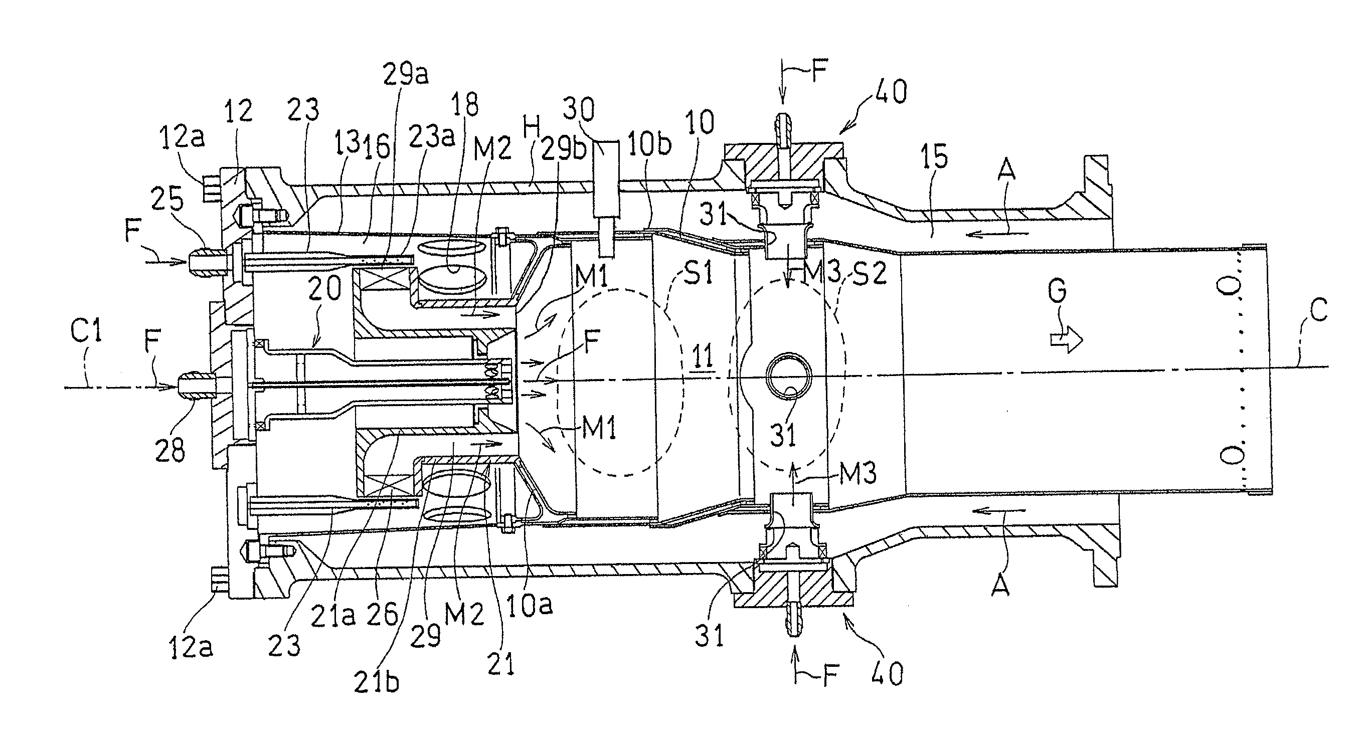
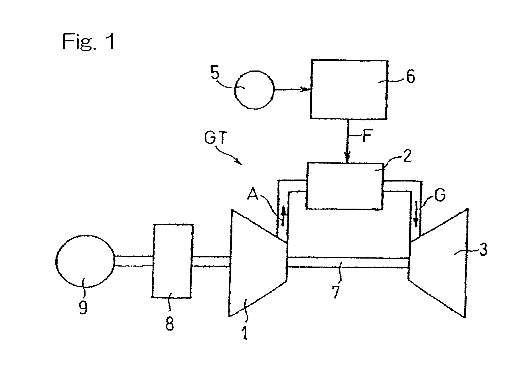
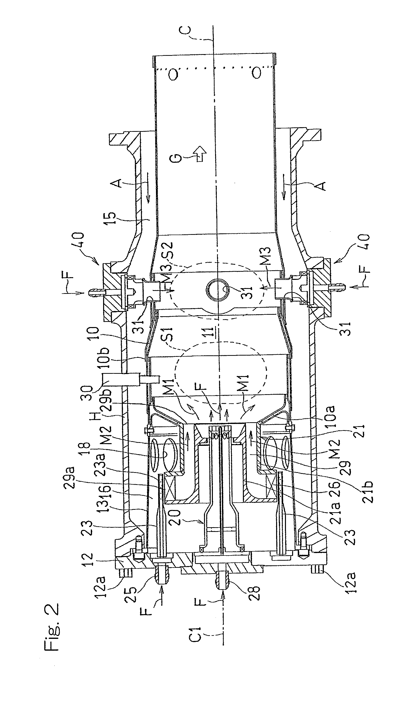
[0028]Hereinafter, a gas turbine combustor designed in accordance with an embodiment of the present invention will be described in detail with reference to the accompanying drawings. Referring to FIG. 1 showing a schematic structure of a gas turbine generator in which the gas turbine combustor of the embodiment is employed, the gas turbine generator GT includes, as principal constituent elements thereof, a compressor 1, a combustor 2 and a turbine 3. The combustor 2 is provided with a fuel supply device 5 and a fuel control device 6. A compressed air A, fed from the compressor 1, and fuel F fed from the fuel supply device 5 through the fuel control device 6 are burned within the combustor 2 to produce a combustion gas G of high temperature and high pressure, which is in turn supplied to the turbine 3 to drive the turbine 3. The compressor 1 is driven by the turbine 3 through a rotary shaft 7. The turbine 3 also drives an electric generator 9 through a reduction gear unit 8.

[0029]As ...


PUM


Abstract

A gas turbine combustor includes a pilot burner, provided at a top portion of a combustion liner having a combustion chamber defined therein, and a main burner of a premixing type disposed adjacent an outer periphery thereof. The pilot burner is provided with an inflow passage, provided in an upstream end portion to allow the compressed air from a radially outer area into a radially inner area, a plurality of fuel supply holes for injecting the fuel into the inflow passage in a direction perpendicular to the flow of the compressed air, a premixing passage for guiding the air-fuel mixture from the inflow passage in an axially downstream direction while the compressed air and the fuel are mixed together, and a plurality of premixed air-fuel mixture injection holes for injecting the premixed air-fuel mixture from the premixing passage into the combustion chamber.

Description

CROSS REFERENCE TO THE RELATED APPLICATION[0001]This application is a continuation application, under 35 U.S.C. §111(a), of international application No. PCT / JP2012 / 070061, filed Aug. 7, 2012, which claims priority to Japanese patent application No. 2011-192549, filed Sep. 5, 2011, the disclosure of which are incorporated by reference in their entirety into this application.BACKGROUND OF THE INVENTION[0002]1. Field of the Invention[0003]The present invention relates to a gas turbine combustor capable of suppressing the emissions of nitrogen oxides (hereinafter referred to as NOx).[0004]2. Description of Related Art[0005]The gas turbine apparatuses are subjected to severe environmental standards regarding the composition of exhaust gases emitted from a turbine during the operation thereof. In particular, reduction of the emissions of NOx contained in the exhaust gases is sought for. As a method of reducing the NOx emission in the gas turbine apparatus, a technique of injecting water ...

Claims


Application Information

Patent Timeline
Patent Type & Authority Applications(United States)
IPC IPC(8): F23R3/28
CPCF23R3/286F23R3/343F23R3/346F23R2900/00004F23R2900/03343
Inventor MATSUMOTO, KIYOSHIODA, TAKEO
Owner KAWASAKI HEAVY IND LTD
Why Eureka
Try Eureka