Optical module

A technology of optical modules and reflective surfaces, which is applied in the field of optical communications and can solve problems such as the weakening of the stability of optical module products

Active Publication Date: 2018-11-23
HISENSE BROADBAND MULTIMEDIA TECH
View PDF3 Cites 0 Cited by
  • Summary
  • Abstract
  • Description
  • Claims
  • Application Information

AI Technical Summary

Problems solved by technology

[0003] However, the above-mentioned monitoring method needs to add an additional spectroscopic device in the optical module, which increases the process and weakens the stability of the optical module product.

Method used


Image

  • Optical module
  • Optical module
  • Optical module

Examples


Embodiment Construction

[0025] In order to further illustrate the principle and structure of the present invention, preferred embodiments of the present invention will now be described in detail with reference to the accompanying drawings.

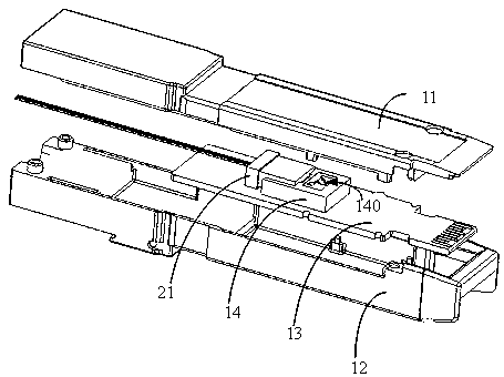
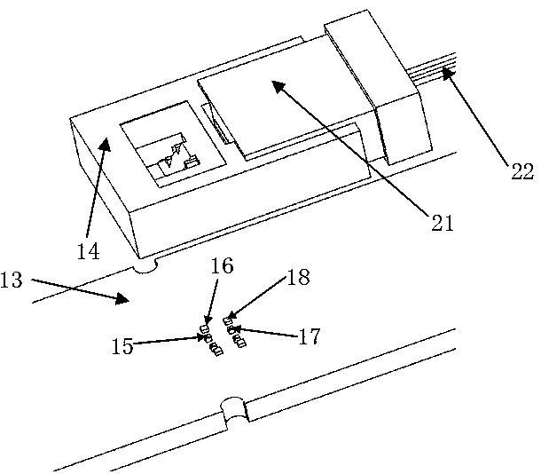
[0026] figure 1 It is a structural schematic diagram of the optical module of the present invention, the optical module includes an upper cover 11, a lower cover 12, a circuit board 13, an optical emission chip integrated on the circuit board 13, an optical monitoring chip, and a cover over the optical emitting chip and the optical monitoring chip. The lens assembly 14. The circuit board 13 , the light emitting chip, the light monitoring chip and the lens assembly 14 are all located in the combined space of the upper cover 11 and the lower cover 12 . The fiber holder 21 is inserted into the housing enclosed by the upper cover 11 and the lower cover 12 , and is snap-connected with the lens assembly 14 .

[0027] The light from the lens assembly is coupled to the...


PUM


Abstract

The invention discloses an optical module and belongs to the field of optical communication. The optical module provided by the embodiment of the invention includes: a circuit board and a lens assembly, and a first light emitting chip, a second light emitting chip, a first light monitoring chip and a second light monitoring chip, which are arranged between the circuit board and the lens assembly and mounted on the surface of the circuit board. The lens assembly is provided with a first reflection surface and the same-side edges of the first reflection surface are provided with a second reflection surface and a third reflection surface. The first reflection surface and the second reflection surface reflect light from the first light emitting chip in different directions and the first reflection surface and the third reflection surface reflect light from the second light emitting chip in different directions; the first light monitoring chip receives light from the second reflection surface and the second light monitoring chip receives light from the third reflection surface. Light split monitoring is realized and the number of arranged light emitting chips is increased.

Description

technical field [0001] The invention relates to the field of optical communication, in particular to an optical module. Background technique [0002] Optical modules are used for photoelectric signal conversion. Generally, during the operation of the optical module, it is necessary to monitor the laser of the optical module to know the working state of the laser. In the traditional technology, a spectroscopic device, such as a filter, is usually placed on the exit direction of the laser to split the beam emitted by the laser into two paths, one of which is transmitted through the spectroscopic device and coupled to the optical fiber, and the other path passes through the spectroscopic device The reflection is incident to the detector of the optical module, and the detector receives the reflected beam and detects the optical power parameters, thereby realizing the monitoring of the state of the laser. [0003] However, the above-mentioned monitoring method needs to add an a...

Claims


Application Information

Patent Timeline
Patent Type & Authority Applications(China)
IPC IPC(8): G02B6/42
CPCG02B6/4214G02B6/428
Inventor 刘旭霞
Owner HISENSE BROADBAND MULTIMEDIA TECH
Why Eureka
Try Eureka