Spiral antenna forming device

A technology for forming a device and a helical antenna, which is applied in the directions of the antenna and the radiating element structure suitable for movable objects, can solve the problems of the inability to guarantee the pitch and the diameter of the helix, and achieve accurate indicators in all aspects of the pitch and meet the design and use. demand, cost savings

Active Publication Date: 2018-11-27
BEIJING AEROSPACE GUANGHUA ELECTRONIC TECH CO LTD
View PDF5 Cites 0 Cited by
  • Summary
  • Abstract
  • Description
  • Claims
  • Application Information

AI Technical Summary

Problems solved by technology

Due to the special material of the antenna, the helical resilience is very strong, and it is difficult to accurately guarantee the pitch and helical diameter of the antenna

Method used


Image

  • Spiral antenna forming device
  • Spiral antenna forming device

Examples


Embodiment Construction

[0021] Below in conjunction with accompanying drawing and specific embodiment the present invention is described in further detail:

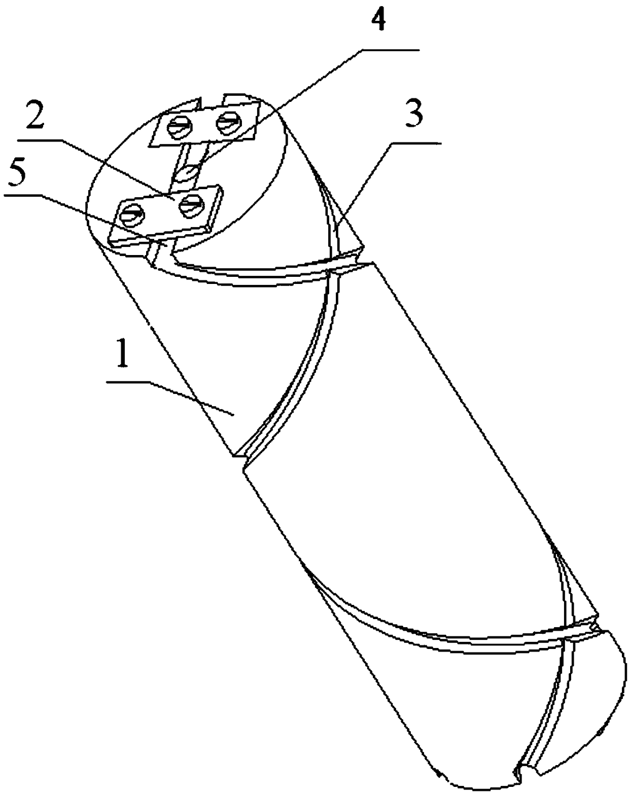
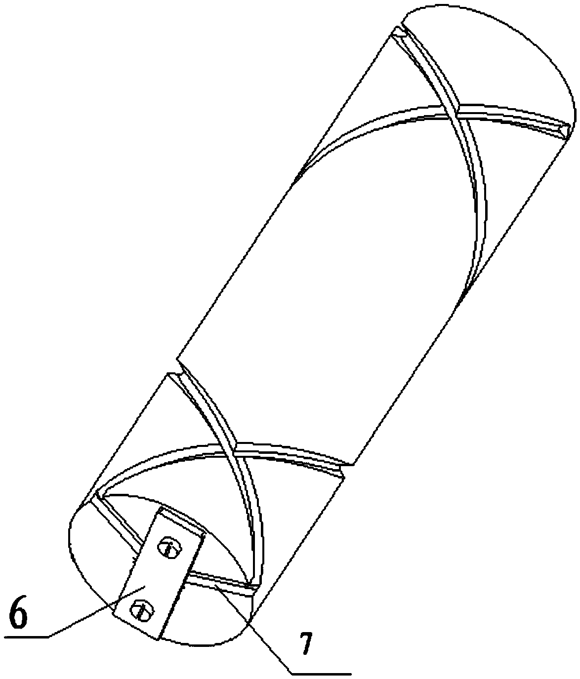
[0022] The present invention provides an effective and accurate spiral antenna forming device. According to the requirements for different welding diameters, lengths and directions of rotation of the spiral antenna, forming bodies 1 with different diameters are designed, and different directions of rotation and lengths are marked on the forming device of the spiral antenna. , and the forming positions of different pitches, to avoid product quality problems due to the strong stress of the antenna helix during the forming process of the helix antenna, and the amount of springback cannot be controlled, so as to achieve stable and accurate antenna helix state.

[0023] The spiral antenna forming device is composed of a forming main body 1, two front fixing plates 2 and a rear fixing plate 6, and the two front fixing plates 2 and the rear fixing plate...


PUM

PropertyMeasurementUnit
Pitchaaaaaaaaaa

Abstract

The invention discloses a spiral antenna forming device, and relates to the field of spiral antenna manufacturing. The device comprises a main forming body, two antenna track fixing grooves, a head fixing groove, two connecting grooves and two tail fixing grooves; the head fixing groove is formed in the axis part of the axial top of the main forming body; the two connecting grooves are linearly distributed in the axial top of the main forming body and communicated with the head fixing groove; the two antenna track fixing grooves are formed in the side wall of the main forming body, and the tops of the two antenna track fixing grooves are communicated with the two connecting grooves respectively; the two tail fixing grooves are formed in the axial bottom of the main forming body, both pointto the center of the main forming body and are communicated with the bottoms of the two antenna track fixing grooves respectively. The spiral antenna forming device is easy to manufacture and convenient to use and operate, the cost is reduced, it is ensured that indexes of various aspects of screw pitches of spiral antennas are accurate, the residual stress in the antenna bending process is removed, it is ensured that no influence is caused during later use, and the quality of the spiral antennas produced in batches is ensured.

Description

technical field [0001] The invention relates to the field of helical antenna manufacturing, in particular to a helical antenna shaping device. Background technique [0002] The realization of certain functions of the rocket receives and transmits digital signals through antennas, and helical antennas need to be installed on devices such as controllers and actuators. It is required that the helical antenna has high precision in the direction of rotation, helix diameter, and pitch. Due to the special material of the antenna, the helical resilience is very strong, and it is difficult to accurately guarantee the pitch and helical diameter of the antenna after trying many methods, especially the production of batch helical antennas, which cannot guarantee a consistent pitch and helical diameter. This leads to quality problems. Contents of the invention [0003] The purpose of the present invention is to overcome the above-mentioned deficiencies in the prior art, and provide a...

Claims


Application Information

Patent Timeline
IPC IPC(8): B21F3/04H01Q1/28H01Q1/36
CPCB21F3/04H01Q1/28H01Q1/36
Inventor 王树三廖盼刘玉秋蒋思焱董坤杰李改鸽李永胜
Owner BEIJING AEROSPACE GUANGHUA ELECTRONIC TECH CO LTD
Why Eureka
Try Eureka