Sapphire substrate flattening method

Active Publication Date: 2014-10-02
DISCO CORP
View PDF4 Cites 2 Cited by
  • Summary
  • Abstract
  • Description
  • Claims
  • Application Information

AI Technical Summary

Benefits of technology

[0009]In the sapphire substrate flattening method according to the present invention, the sapphire substrate obtained by slicing the sapphire single-crystal ingot is annealed to thereby remove the residual stress left in the sapphire s

Problems solved by technology

However, a sapphire ingot is hard and a large stress is therefore generated in slicing the sapphire ingot by using a wire saw.
As a result, a

Method used


Image

  • Sapphire substrate flattening method
  • Sapphire substrate flattening method
  • Sapphire substrate flattening method

Examples


Example

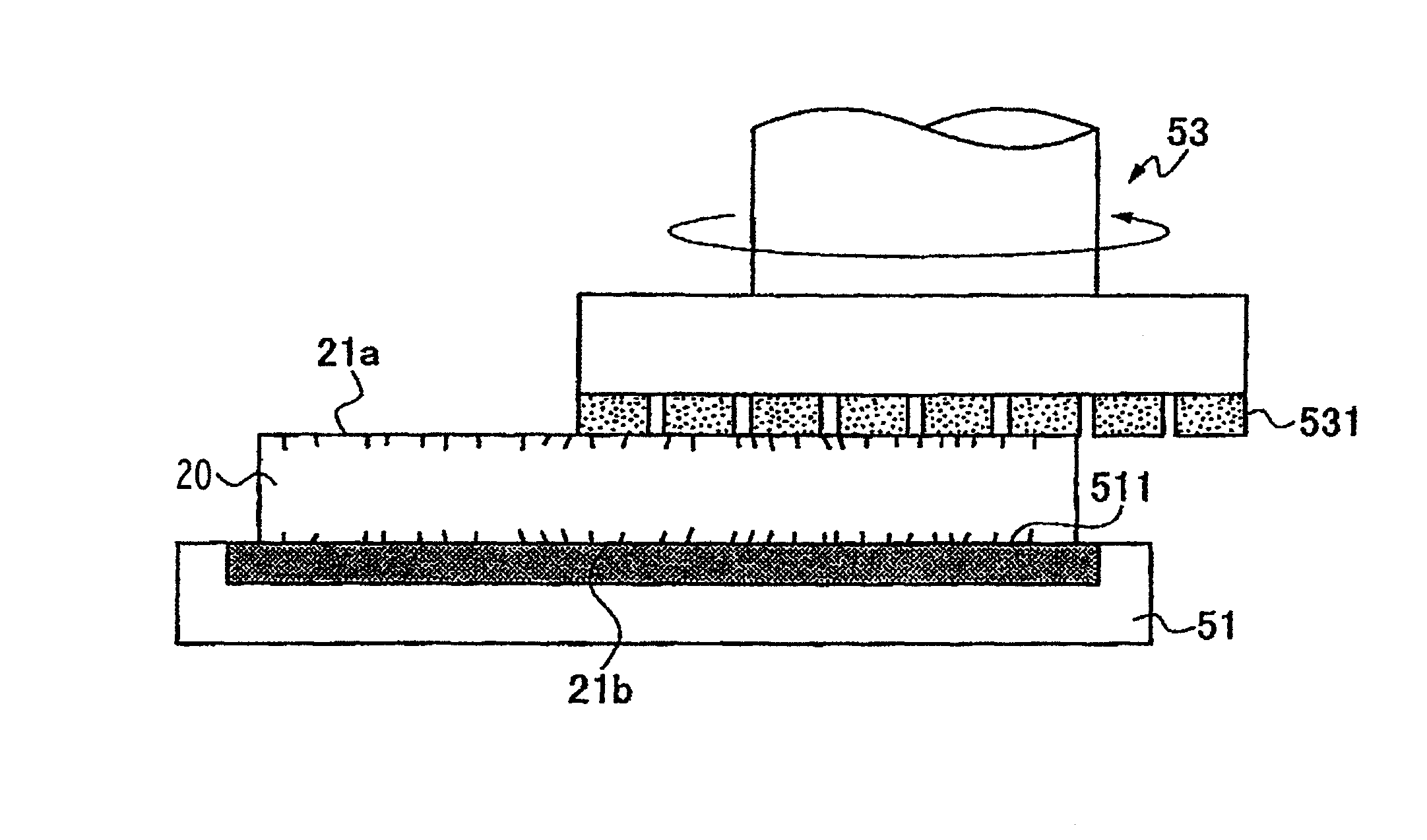
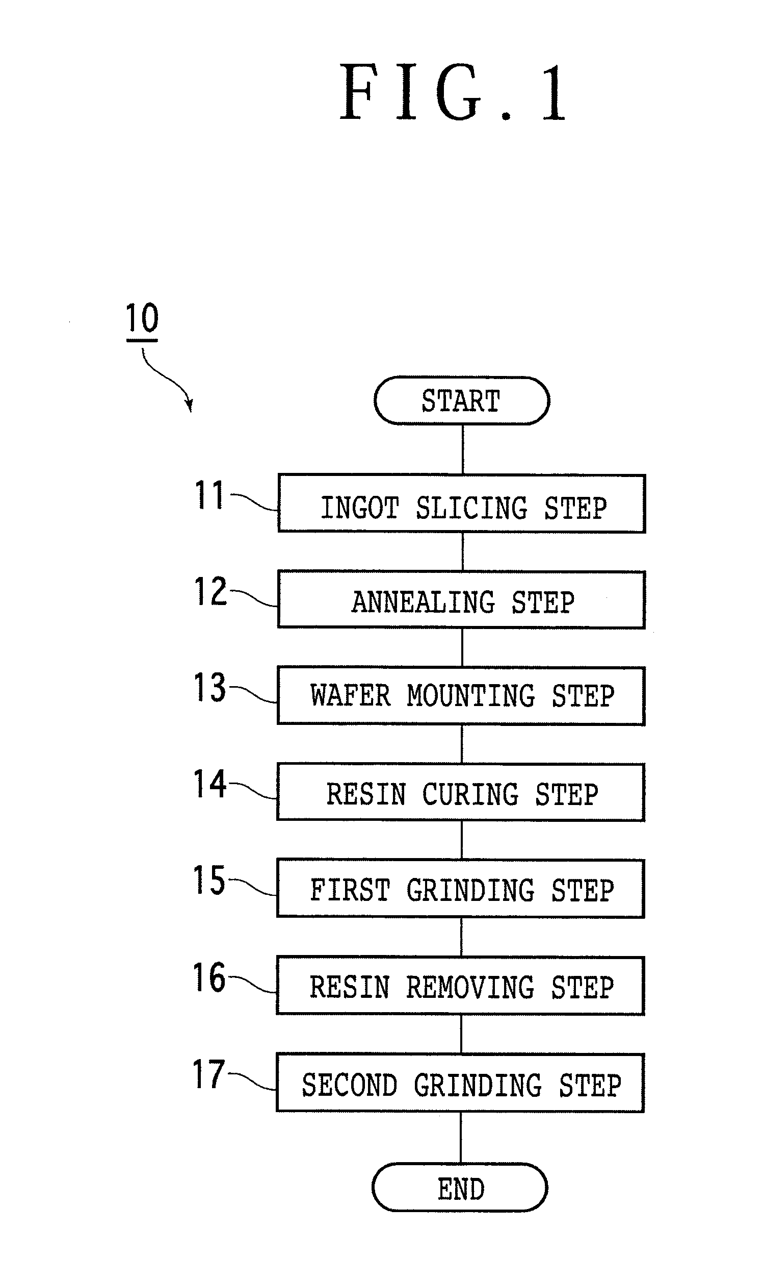
[0021]Referring to FIG. 1, there is shown a flow 10 of the sapphire substrate flattening method according to the present invention. The flow 10 has the following procedure. An ingot slicing step 11 is first performed to slice a sapphire single-crystal ingot into sapphire substrates by using a wire saw. An annealing step 12 is next performed to anneal the sapphire substrates obtained by the ingot slicing step 11. A wafer mounting step 13 is next performed to mount each sapphire substrate processed by the annealing step 12 on a stage having a holding surface in the condition where one side surface (first surface) of this sapphire substrate is in contact with the holding surface of the stage through a liquid resin. A resin curing step 14 is next performed to cure the liquid resin adhering to the sapphire substrate processed by the wafer mounting step 13. A first grinding step 15 is next performed to grind the other side surface (second surface) of the sapphire substrate processed by th...


PUM


Abstract

A sapphire substrate flattening method including an ingot slicing step of slicing a sapphire single-crystal ingot to obtain a sapphire substrate, an annealing step of annealing the sapphire substrate, a wafer mounting step of mounting the sapphire substrate processed by the annealing step on a stage having a holding surface in the condition where a first surface of the sapphire substrate is in contact with the holding surface of the stage through a liquid resin, a resin curing step of curing the liquid resin, a first grinding step of grinding a second surface of the sapphire substrate opposite to the first surface, a resin removing step of removing the liquid resin cured on the first surface of the sapphire substrate, and a second grinding step of grinding the first surface of the sapphire substrate.

Description

BACKGROUND OF THE INVENTION[0001]1. Field of the Invention[0002]The present invention relates to a method of flattening a sapphire substrate obtained by slicing an ingot.[0003]2. Description of the Related Art[0004]The surface of a wafer obtained by slicing an ingot with a wire saw has fine undulation (irregularities) and strain. To remove such undulation and strain, both sides of the wafer are ground and polished to be flattened. For example, a wafer flattening method described in Japanese Patent Laid-Open No. 2011-151099 includes the steps of measuring the undulation of a wafer, applying a liquid resin to a film to form a resin layer on the film, attaching one side surface of the wafer to the resin layer, selectively applying ultrasonic waves to the wafer according to the undulation measured above to thereby partially reduce the viscosity of the liquid resin and restore the undulation of the wafer, curing the liquid resin, and grinding the other side surface of the wafer to remove...

Claims


Application Information

Patent Timeline
IPC IPC(8): H01L21/02
CPCH01L21/02013B24B7/228H01L21/02008
Inventor KUROKAWA, HIROSHI
Owner DISCO CORP
Why Eureka
Try Eureka