Method of correcting head suspension, method of manufacturing head suspension, head suspension, and method of processing thin plate

Active Publication Date: 2009-07-23
NHK SPRING CO LTD
View PDF13 Cites 1 Cited by
  • Summary
  • Abstract
  • Description
  • Claims
  • Application Information

AI Technical Summary

Benefits of technology

[0012]An object of the present invention is to provide a method of correcting a head suspension, a method of manufacturing a head suspension, a head suspension, and a method of processing a thin plate, capable of precisely correcting an objective item even when correcting the objective item a plurality of times.
[0013]In order to accomplish the object, an aspect of the present invention provides a method of correcting a head suspension before or after mounting a read/write head on the head suspension. The method includes

Problems solved by technology

Mechanically holding and correcting the outrigger needs a jig specifically prepared for the outrigger and a long time to move the jig, hold the outrigger, and process the outrigger.
Namely, correcting a head suspension generally involves many steps and a long time.
There is a possibility that a magnetic head already assembled with a head suspension

Method used


Image

  • Method of correcting head suspension, method of manufacturing head suspension, head suspension, and method of processing thin plate
  • Method of correcting head suspension, method of manufacturing head suspension, head suspension, and method of processing thin plate
  • Method of correcting head suspension, method of manufacturing head suspension, head suspension, and method of processing thin plate

Examples


Example

[0024]A method of correcting a head suspension, a method of manufacturing a head suspension, a head suspension, and a method of processing a thin plate according to embodiments of the present invention will be explained in detail with reference to the drawings.

[0025]First, a head suspension correcting apparatus employed by the present invention will be explained.

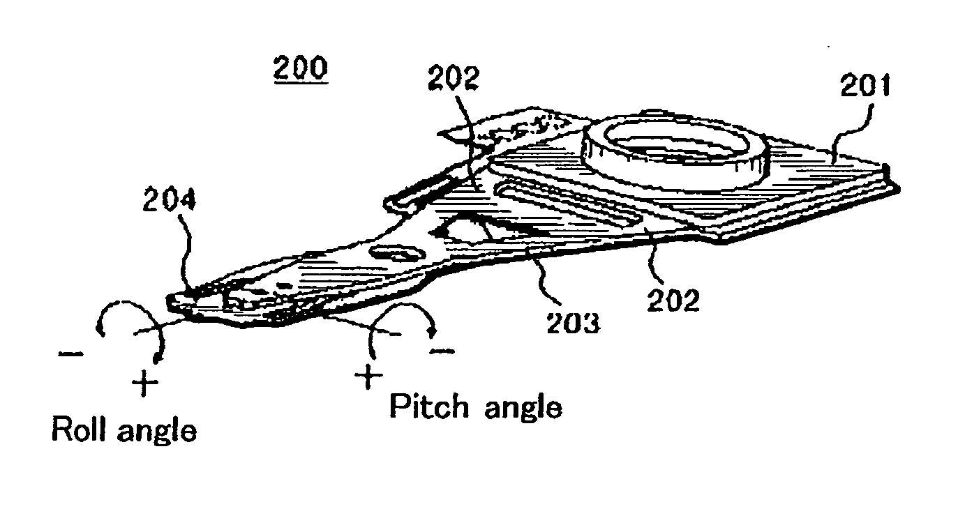
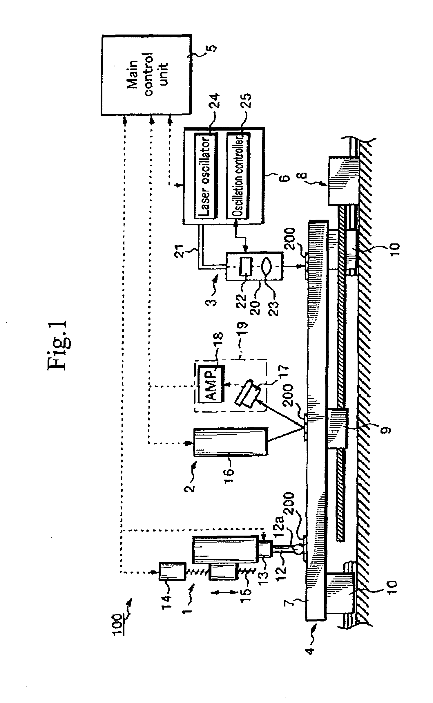
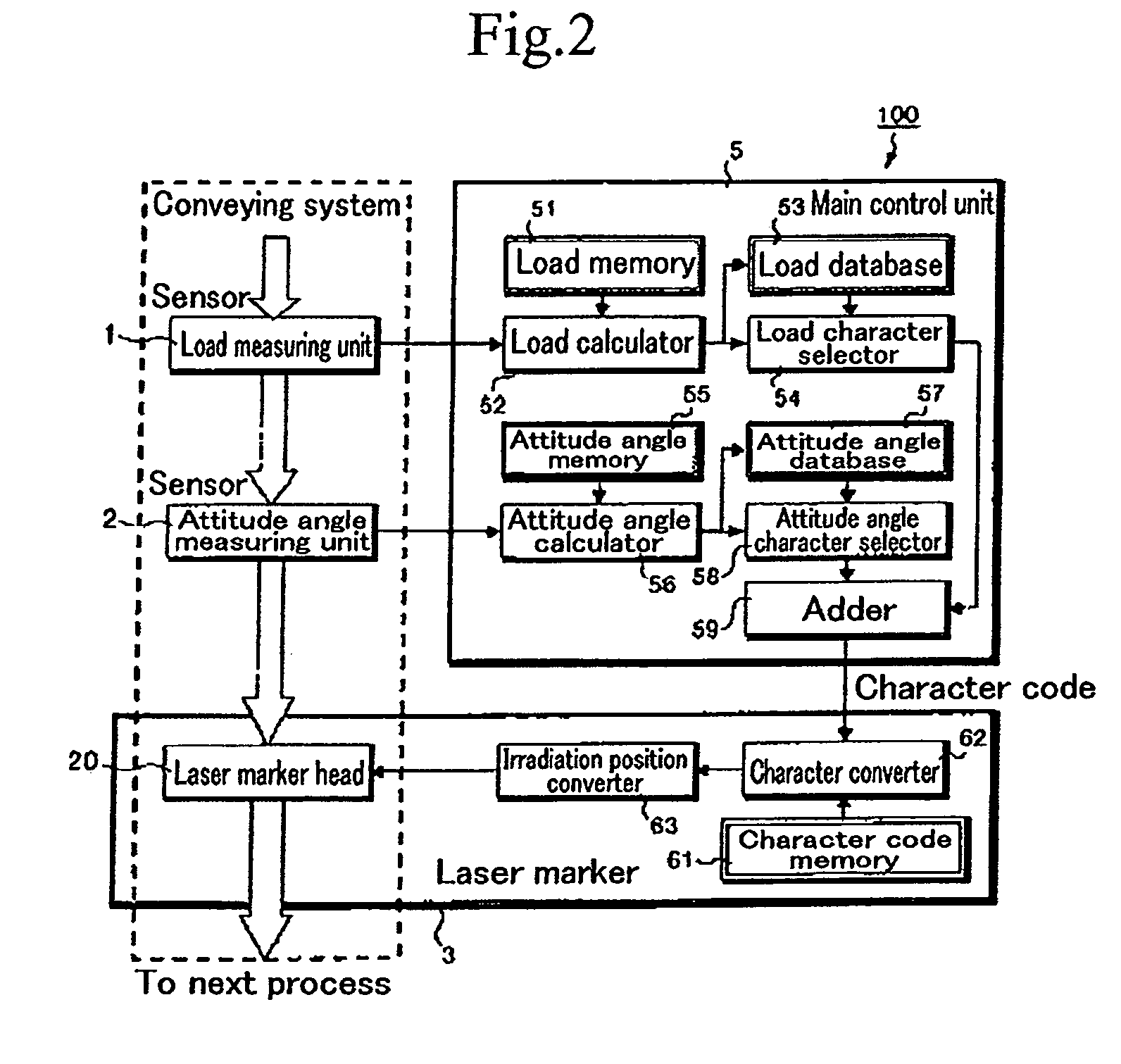
[0026]FIG. 1 is a general view showing the head suspension correcting apparatus, FIG. 2 is a functional block diagram showing the apparatus of FIG. 1, and FIG. 3 is an explanatory view showing a head suspension set in the apparatus of FIG. 1, the head suspension being corrected according to the present invention.

[0027]In FIG. 1, the head suspension correcting apparatus 100 is employed to correct the load and attitude angle of a head suspension due to bending. The apparatus 100 includes a load measuring unit 1, an attitude angle measuring unit 2, a laser marker 3, a conveying unit 4, and a main control unit 5.

[0028]The convey...


PUM

PropertyMeasurementUnit
Residual stressaaaaaaaaaa

Abstract

A method corrects a head suspension by irradiating an objective part of the head suspension with a laser beam. The method is capable of precisely correcting the head suspension even when correcting the head suspension a plurality of times. The method removes residual stress created by the preceding correction from the head suspension, and then, carries out the next correction. Accordingly, the method can precisely correct the objective part of the head suspension with a laser beam even if the objective part has once been irradiated with a laser beam in the preceding correction.

Description

BACKGROUND OF THE INVENTION[0001]1. Field of the Invention[0002]The present invention relates to a method of correcting the load or attitude angle of a head suspension that supports a magnetic head slider in a hard disk drive, a method of manufacturing such a head suspension, the head suspension itself, and a method of processing a thin plate. In particular, the present invention relates to a method of correcting a head suspension, capable of precisely correcting the load or attitude angle of the head suspension even when correcting the head suspension a plurality of times, a method of manufacturing a head suspension with the use of the correcting method, the head suspension thus manufactured, and a thin plate processing method employing the correcting method.[0003]2. Description of Related Art[0004]The recording density of hard disk drives has drastically improved in recent years, and accordingly, a precision requirement for head suspensions for supporting magnetic heads in the har...

Claims


Application Information

Patent Timeline
IPC IPC(8): G11B11/00
CPCG11B5/4813G11B5/6011G11B5/581
Inventor FURUTA, EIJIRO
Owner NHK SPRING CO LTD
Why Eureka
Try Eureka